
Related Manuals for CTS FOS-3124 SERIES


Summary of Contents for CTS FOS-3124 SERIES
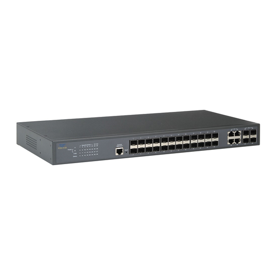
- Page 1 FOS-3124 SERIES 20 PORTS 100/1000BASE-X SFP WITH 4 COMBO PORTS (10/100/1000BASE-T, 100/1000BASE-X SFP) UPLINK MANAGED SWITCH Network Management User’s Manual Version 1.0...
-
Page 2: Copyright Statement
Trademarks CTS is a registered trademark of Connection Technology Systems Inc.. Contents subject to revision without prior notice. All other trademarks remain the property of their owners. Copyright Statement Copyright Connection Technology Systems Inc. This publication may not be reproduced as a whole or in part, in any way whatsoever unless prior consent has been obtained from Connection Technology Systems Inc.. -
Page 3: Table Of Contents
Table of Content 1. INTRODUCTION ....................... 8 1.1 Interface ........................8 1.2 Management Options ....................9 1.3 Management Software ....................10 1.4 Management Preparations ..................11 2. Command Line Interface (CLI) ..................14 2.1 Using the Local Console .................... 14 2.2 Remote Console Management - Telnet .............. - Page 4 2.6.10 IP Command ...................... 50 2.6.11 LLDP Command....................57 2.6.12 MAC Command ....................59 2.6.13 Management Command ..................60 2.6.14 Mirror Command ....................61 2.6.15 MVR Command ....................62 2.6.16 NTP Command ....................63 2.6.17 QoS Command ....................64 2.6.18 Security Command .................... 67 2.6.19 Spanning Tree Command ..................
- Page 5 4.4.1 Switch Configuration ..................106 4.4.2 Port Configuration ....................108 4.4.3 Link Aggregation ....................108 4.4.3.1 Trunk Mode Configuration ................109 4.4.3.2 Port Trunk Configuration ................110 4.4.3.3 LACP Port Configuration ................111 4.4.4 Rapid Spanning Tree ..................113 4.4.4.1 RSTP Switch Settings ................. 114 4.4.4.2 RSTP Aggregated Port Settings ..............
- Page 6 4.4.11.3 IPMC Segment ..................141 4.4.11.4 IPMC Profile ....................143 4.4.11.5 IGMP Filtering ................... 144 4.4.12 Static Multicast Configuration ................145 4.4.13 MVR ......................... 146 4.4.13.1 MVR Settings .................... 148 4.4.13.2 MVR Group ....................149 4.4.14 Security Configuration ..................150 4.4.14.1 DHCP Option 82 Settings ................
- Page 7 4.5.8.1 IGMP Snooping Status ................183 4.5.8.2 IGMP Group Table ..................184 4.5.9 MAC Address Table ................... 184 4.5.10 SFP Information ....................185 4.5.10.1 SFP Port Info ..................... 185 4.5.10.2 SFP Port State ..................186 4.5.11 DCHP Snooping ....................187 4.5.12 LLDP Status .....................
-
Page 8: Introduction
1. INTRODUCTION Thank you for using the 20 Ports 100/1000 Base-X SFP with 4 Combo Ports Uplink Managed Switch that is specifically designed for SMB (small and medium businesses), SME and for FTTx applications. The Managed Switch provides a built-in management module that enables users to configure and monitor the operational status both locally and remotely. -
Page 9: Management Options
Figure 2-2: Model 2 Rear Panel Battery DC 12V Figure 2-3: Model 3 Rear Panel Battery DC 12V Battery DC 12V Figure 2-4: Model 4 Rear Panel Battery DC 12V Figure 2-5: Model 5 Rear Panel 1.2 Management Options Switch management options available are listed below: ... -
Page 10: Management Software
SSH Management SSH Management supports encrypted data transfer to prevent the data from being “stolen” due to remote management. You can use PuTTY, a free and open source terminal emulator application which can act as a client for the SSH, to gain access to the Managed Switch. -
Page 11: Management Preparations
SNMP Management System Standard SNMP-based network management system is used to manage the Managed Switch through the network remotely. When you use a SNMP-based network management system, the Managed Switch becomes one of the managed devices (network elements) in that system. The Managed Switch management module contains an SNMP agent that will respond to the requests from the SNMP-based network management system. - Page 12 SFP slot for 3.3V mini GBIC module supports hot swappable SFP fiber transceiver. Before connecting the other switches, workstation or Media Converter, make sure both side of the SFP transfer are with the same media type, for example, 1000Base-SX to 1000Base-SX, 1000Bas-LX to 1000Base-LX, and check the fiber-optic cable type matches the SFP transfer model.
- Page 13 A subnet mask is a filtering system for IP addresses. It allows you to further subdivide your network. You must use the proper subnet mask for the proper operation of a network with subnets defined. MIB for Network Management Systems Private MIB (Management Information Bases) is provided for managing the Managed Switch through the SNMP-based network management system.
-
Page 14: Command Line Interface (Cli)
2. Command Line Interface (CLI) This chapter introduces you how to use Command Line Interface (CLI), specifically in: Local Console Telnet Configuring the system Resetting the system The interface and options in Local Console and Telnet are the same. The major difference is the type of connection and the port that is used to manage the Managed Switch. -
Page 15: Remote Console Management - Telnet
2.2 Remote Console Management - Telnet You can manage the Managed Switch via Telnet session. However, you must first assign a unique IP address to the Switch before doing so. Use the Local Console to login the Managed Switch and assign the IP address for the first time. Follow these steps to manage the Managed Switch through Telnet session: Step 1. -
Page 16: General Commands
2.3.1 General Commands This section introduces you some general commands that you can use in User, Enable, and Configuration Mode, including “help”, “exit”, “history” and “logout”. Entering the command… To do this… Available Modes User Mode Obtain a list of available help Privileged Mode commands in the current mode. -
Page 17: Command Format
2.3.3 Command Format While in CLI, you will see several symbols very often. As mentioned above, you might already know what “>”, “#” and (config)# represent. However, to perform what you intend the device to do, you have to enter a string of complete command correctly. For example, if you want to assign an IP address for the Managed Switch, you need to enter the following command with the required parameter and IP, subnet mask and default gateway: Switch(config)#ip address [A.B.C.D] [255.X.X.X] [A.B.C.D]... -
Page 18: Login Username & Password
[0-7] 802.1p_list Specify one value, more than one value or a [0-63] dscp_list range of values. Example 1: specifying one value Switch(config)#qos 802.1p-map 1 0 Switch(config)#qos dscp-map 10 3 Example 2: specifying three values (separated by commas) Switch(config)#qos 802.1p-map 1,3 0 Switch(config)#qos dscp-map 10,13,15 3 Example 3: specifying a range of values (separated by a hyphen) -
Page 19: User Mode
Forgot Your Login Username & Password If you forget your login username and password, you can use the “reset button” on the front panel to set all configurations back to factory defaults. Once you have performed system reset to defaults, you can login with default username and password. Please note that if you use this method to gain access to the Managed Switch, all configurations saved in Flash will be lost. -
Page 20: Privileged Mode
2.5 Privileged Mode The only place where you can enter the Privileged (Enable) Mode is in User Mode. When you successfully enter Enable Mode (this mode is password protected), the prompt will be changed to Switch# (the model name of your device together with a pound sign). Enter the question mark (?) or help command to view a list of commands available for use. -
Page 21: Firmware Command
[password] [user_name] Enter the username for FTP server login. [password] Enter the password for FTP server login. Switch# copy-cfg to [A.B.C.D] Enter the IP address of your TFTP server. tftp [A.B.C.D] [file name] Enter the configuration file name that you want to [file_name] backup. -
Page 22: Ping Command
2.5.3 Ping Command Command Parameter Description Switch# ping [A.B.C.D] Enter the IP address that you would like to ping. [A.B.C.D] [-s size] [- [-s size] Enter the packet size that would be sent. The r repeat] [-t timeout] allowable packet size is from 8 to 4000 bytes. (optional) [-r repeat] Enter the number of times that ping packets are... -
Page 23: Configuration Mode
2.6 Configuration Mode When you enter “configure” or “config” and press “Enter” in Privileged Mode, you will be directed to Global Configuration Mode where you can set up advanced switching functions, such as QoS, VLAN and storm control security globally. All commands entered will be applied to running-configuration and the device‟s operation. -
Page 24: No Command
Switch(config)# interface 1-3 Enter three continuous interfaces. Use a Switch(config-if-1-3)# hyphen to signify a range of interface numbers. In this example, interface 1, 2, and 3 will apply commands entered. Switch(config)# interface 1,3-5 Enter a single interface number together with Switch(config-if-1,3-5)# a range of interface numbers. - Page 25 Company Name: Display a company name for this Managed Switch. Use “switch-info company-name [company-name]” command to edit this field. System Object ID: Display the predefined System OID. System Contact: Display contact information for this Managed Switch. Use “switch-info sys-contact [sys-contact]” command to edit this field. System Name: Display a descriptive system name for this Managed Switch.
-
Page 26: Interface Command
4. Show default, running and startup configurations Refer to “show default-setting command”, “show running-config command” and “show start- up-config command” sections. 2.6.4 Interface Command Use “interface” command to set up configurations of several discontinuous ports or a range of ports. Command Parameter Description... -
Page 27: Acl Command
Switch(config-if-PORT-PORT)# Administratively enable the selected ports‟ no shutdown status. Show command Switch(config)# show interface Show each interface‟s port configuration including media type, forwarding state, speed, duplex mode, flow control and link up/down status. Switch(config)# show interface [port_list] Show the selected interface‟s port [port_list] configuration. - Page 28 Switch(config-acl-RULE)# [dest_mac] Define the destination MAC filtering frame-type any [dest_mac] type. “any”: Specify “any” to filter any kind of traffic. “uc”: Specify “uc” to filter unicast traffic. “mc”: Specify “mc” to filter to filter multicast traffic. “bc”: Specify “bc” to filter broadcast traffic.
- Page 29 Specify “any” to apply ACL rule to both [opcode] reply and request frames; “reply” to denote reply frames; “request” to denote request frames. [source_ip] This is sender IP filtering function. Specify “any” to filter frames from any sender IP addresses. Or, specify either a host IP address (x.x.x.x).
- Page 30 [rarp_dmac_match] This is to configure whether RARP destination MAC sent and received are matched or not. “any”: Specify “any” to denote both a match and not a match. “0”: Denote not a match. “1”: Denote a match. “any”: Specify “Any” to indicate a [length_check] match and not a match.
- Page 31 Switch(config-acl-RULE)# [source_mac] Define source MAC address. frame-type ethernet-type “any”: Specify “any” to apply ACL rule [source_mac] [mac_mask] [dest_mac] [mac_mask] to any source MAC addresses. [ether_type] “xx:xx:xx:xx:xx:xx”: Specify a specific source MAC address. [mac_mask] Specify MAC mask. “any”: Specify “any” mean any MAC mask.
- Page 32 Switch(config-acl-RULE)# [dest_mac] Define the destination MAC filtering frame-type icmp type. [dest_mac] [icmp_type] “any”: Specify “any” to filter any kind [icmp_code] [source_ip] [ip_mask] [dest_ip] of traffic. [ip_mask] [ip_ttl] “uc”: Specify “uc” to filter unicast [ip_fragment] [ip_option] traffic. “mc”: Specify “mc” to filter to filter multicast traffic.
- Page 33 [ip_mask] Define destination IP mask. “any”: Specify “any” to mean any IP mask. “255.255.0.0”: Specify a specific IP mask. [ip_ttl] Specify IP TTL bit. “any”: Specify “any” to denote the value which is either zero or not zero. “0”: Specify “0” to indicate that the TTL filed in IPv4 header is 0.
- Page 34 [protocol_id] This parameter is to show the protocol number defined in the protocol field of the IPv4 packet. Specify “any” to denote any protocols; specify “1-255” to denote different defined protocols. [source_ip] This is sender IP filtering function. Specify “any” to filter frames from any sender IP addresses.
- Page 35 [ip_option] Specify IP option bit. “any”: Specify “any” to denote the value which is either 0 or not 0. “0”: Specify “0” to indicate that the IPv4 is 5 bytes. “1”: Specify “1” to indicate that the IPv4 header is bigger than 5 bytes. Switch(config-acl-RULE)# [dest_mac] Define destination MAC address type.
- Page 36 [source_ip] This is sender IP filtering function. Specify “any” to filter frames from any sender IP addresses. Or, specify a host IP address (x.x.x.x). [ip_mask] Define source IP mask. “any”: Specify “any” to mean any IP mask. “255.255.0.0”: Specify a specific IP mask.
- Page 37 [ip_option] Specify IP option bit. “any”: Specify “any” to denote the value which is either 0 or not 0. “1”: Specify “1” to indicate that the IPv4 header is bigger than 5 bytes; “0”: Specify “0” to indicate that the IPv4 is 5 bytes.
- Page 38 Switch(config-acl-RULE)# [dest_mac] Define destination MAC address type. frame-type udp [dest_mac] “any”: Specify “any” to apply ACL rule [source_port] [dest_port] [source_ip] [ip_mask] to any destination MAC addresses. [dest_ip] [ip_mask] [ip_ttl] “uc”: Specify “uc” to apply ACL rule to [ip_fragment] [ip_option] unicast traffic. “mc”: Specify “mc”...
- Page 39 [ip_mask] Define source IP mask. “any”: Specify “any” to mean any IP mask. “255.255.0.0”: Specify a specific IP mask. [dest_ip] This is destination IP filtering function. “any”: Specify “any” to filter frames to any target IP addresses. “x.x.x.x”: Specify either a host IP address.
- Page 40 [ip_option] Specify IP option bit. “any”: Specify “any” to denote the value which is either 0 or not 0. “1”: Specify “1” to indicate that the IPv4 header is bigger than 5 bytes; “0”: Specify “0” to indicate that the IPv4 is 5 bytes.
- Page 41 No command Switch(config-acl-RULE)# Permit the action. no action Switch(config-acl-RULE)# Disable port-copy function. no action port-copy Switch(config-acl-RULE)# Disable rate-limiter function. no action rate-limiter-id Switch(config-acl-RULE)# Activate the interface. no action shutdown Switch(config-acl-RULE)# Reset the frame type back to the no frame-type default value. Switch(config-acl-RULE)# Reset the ingress port to the default no ingress-port...
- Page 42 Use “interface” command to configure ACL rules for a group of ports Command Parameter Description Switch(config)# interface [port_list] [port_list] Enter several discontinuous port numbers separated by commas or a range of ports with a hyphen. For example:1,3 or 2-4 Switch(config-if-PORT-PORT)# acl [deny] Deny the specified interfaces‟...
-
Page 43: Archive Command
2.6.6 Archive Command Backup a copy of configuration file to FTP or TFTP server automatically. Archive command Parameter Description Switch(config)# archive auto- To enable auto-backup function. backup Switch(config)# archive auto- [A.B.C.D] Specify the IP address of the FTP server backup path ftp [A.B.C.D] to which a copy of configuration file will [directory] [user_name] be backed up. -
Page 44: Channel-Group Command
2.6.7 Channel-Group Command 1. Configure a static link aggregation group (LAG). Command Parameter Description Switch(config)# channel-group [group_name] Specify a name for this link trunking [group_name] aggregation group. Use “interface” command to Switch(config)# interface [port_list] [port_list] [group_name] configure a group of ports‟ link Switch(config-if-PORT-PORT)# aggregation link membership. - Page 45 2. Use “Interface” command to configure link aggregation groups dynamically (LACP). Channel-group & Interface Parameter Description command Switch(config)# interface [port_list] [port_list] Enter several discontinuous port numbers separated by commas or a range of ports with a hyphen. For example:1,3 or 2-4 Switch(config-if-PORT-PORT)# Enable LACP on the selected channel-group lacp...
-
Page 46: Loop Detection Command
2.6.8 Loop Detection Command Command Parameter Description Switch(config)# loop-detection Enable Loop Detection function. Switch(config)# loop-detection [0-180] Set up Loop Detection time interval interval [1-180] from 1 to 180 seconds. Switch(config)# loop-detection [1-1440] Set up Loop Detection unlock time unlock-interval [1-1440] interval fromo 1440 minutes. -
Page 47: Dot1X Command
2.6.9 Dot1x Command Command Parameter Description Switch(config)# dot1x Enable dot1x function. When enabled, the Managed Switch acts as a proxy between the 802.1X- enabled client and the authentication server. In other words, the Managed Switch requests identifying information from the client, verifies that information with the authentication server, and relays the response to the client. - Page 48 Show command Switch(config)# show dot1x Show or verify 802.1x settings. Switch(config)# show dot1x Show or verify each interface‟s interface 802.1x settings including port status and authentication status. Switch(config)# show dot1x [port_list] Show or verify the selected interface [port_list] interfaces‟ 802.1x settings including port status and authentication status.
- Page 49 “authorized”: This forces the Managed Switch to grant access to all clients, both 802.1X-aware and 802.1x-unaware. No authentication exchange is required. By default, all ports are set to “authorized”. Switch(config-if-PORT-PORT)# Re-authenticate the selected dot1x reauthenticate interfaces. No command Switch(config)# interface [port_list] [port_list] Enter several discontinuous port numbers separated by commas or a...
-
Page 50: Ip Command
2.6.10 IP Command 1. Set up an IP address of the Managed Switch or configure the Managed Switch to get an IP address automatically from DHCP server. IP command Parameter Description Switch(config)# ip [A.B.C.D] Enter the desired IP address for your Managed address [A.B.C.D] Switch. - Page 51 Show command Switch(config)# show ip address Show the current IP configurations or verify the configured IP settings. Switch(config)# show ip dhcp Show each interface‟s DHCP Snooping snooping settings. Switch(config)# show ip dhcp Show each port‟s DHCP Snooping Option snooping interface 82 and trust port settings.
- Page 52 DHCP & Interface Example Switch(config)# interface 1-3 Enter several discontinuous port numbers separated by commas or a range of ports with a hyphen. For example:1,3 or 2-4 Switch(config-if-1-3)# ip dhcp snooping Set the selected interfaces to DHCP Option option 82 Relay Agent. Switch(config-if-1-3)# ip dhcp snooping trust Set the selected interfaces to DHCP Option 82 trust ports.
- Page 53 Switch(config)# ip igmp [1-6000] Specify the maximum response time. This snooping max-response-time [1- 1/10secs determines the maximum amount of time 6000] 1/10secs allowed before sending an IGMP response report. Switch(config)# ip igmp [port_list] Specify multicast router ports. snooping mcast-router [port_list] Switch(config)# ip igmp [1-6000] Specify Query time interval.
- Page 54 5. Configure IGMP Filtering policies. IGMP Filtering command Parameter Description Switch(config)# ip igmp filter Enable IGMP Filtering function. Switch(config)# ip igmp [1-400] Specify a segment ID. segment [1-400] Switch(config-segment-ID)# [segment_name] Specify a name for this segment. name [segment_name] Switch(config-segment-ID)# [E.F.G.H] Specify a multicast IP range.
- Page 55 6. Use “Interface” command to configure a group of ports’ IGMP Filtering function. IGMP & Interface Command Parameter Description Switch(config)# interface [port_list] Enter several discontinuous port [port_list] numbers separated by commas or a range of ports with a hyphen. For example:1,3 or 2-4 Switch(config-if-PORT-PORT)# ip Enable IGMP Filter on the selected...
- Page 56 Switch(config-if-PORT-PORT)# Set the maximum number of no ip igmp max-groups multicast streams back to the factory default (512 channels). Switch(config-if-PORT-PORT)# [E.F.G.H] Remove this static multicast IP to no ip igmp static-multicast-ip VLAN entry. [E.F.G.H] vlan [1-4094] Specify static multicast IP address. [1-4094] Specify a VLAN ID.
-
Page 57: Lldp Command
Switch(config-if-1-3)# ip igmp static-multicast-ip Create a static multicast IP to VLAN 224.10.0.5 vlan 50 entry. 2.6.11 LLDP Command LLDP stands for Link Layer Discovery Protocol and runs over data link layer. It is used for network devices to send information about themselves to other directly connected devices on the network. - Page 58 Switch(config)# no lldp packets Reset the packets-to-be-sent value back to the default setting. Switch(config)# no lldp tlv-select Disable Capability attribute to be sent. capability Switch(config)# no lldp tlv-select Disable Management Address attribute to be sent. management-address Switch(config)# no lldp tlv-select port- Disable Port Description attribute to be sent.
-
Page 59: Mac Command
Show command Switch(config)# show lldp Show or verify LLDP configurations. 2.6.12 MAC Command Set up MAC address table aging time. Entries in the MAC address table containing source MAC addresses and their associated ports will be deleted if they are not accessed within aging time. -
Page 60: Management Command
vlan [1-4094] [1-4094] Specify the VLAN where the packets with the Destination MAC address can be forwarded. Switch(config-if-PORT- Enable MAC learning function. PORT)# mac learning No command Switch(config-if-PORT- [xx:xx:xx:xx:xx:xx] Remove the specified MAC address PORT)# no mac address- from the address table. table static-mac [1-4094] Specify the VLAN to that the specified... -
Page 61: Mirror Command
Switch(config)# management To manage the Managed Switch via SSH. Switch(config)# management To manage the Managed Switch via Web management. No command Switch(config)# no management console Disable console management. timeout Switch(config)# no management telnet Disable Telnet management. Switch(config)# no management telnet port Set Telnet port back to the default setting. -
Page 62: Mvr Command
2.6.15 MVR Command Command Parameter Description Switch(config)# mvr Enable MVR function. Switch(config)# mvr vlan [1-4094] [1-4094] Specify a VID (1~4094) to create a MVR VLAN. Switch(config)# mvr group [1-4094] [1-4094] Specify a registered MVR VID (1~4094) [E.F.G.H] [E.F.G.H] and add specify the multicasting channel that would belong to MVR VLAN. -
Page 63: Ntp Command
2.6.16 NTP Command Command Parameter Description Switch(config)# ntp Enable the Managed Switch to synchronize the clock with a time server. Switch(config)# ntp daylight- Enable the daylight saving function. saving Switch(config)# ntp offset [1-2] [1-2] Offset 1 hour or 2 hours for daylight saving function. -
Page 64: Qos Command
Switch(config)# ntp syn-interval 6000 Set the synchronization interval to 6000 minutes. Switch(config)# ntp time-zone 4 Set the time zone to GMT-8:00 Vancouver. 2.6.17 QoS Command 1. Set up QoS Control List (QCL). QCL command Description Parameter Switch(config)# qos qcl [1-24] [1-24] Create a QoS control list for traffic classification. - Page 65 Switch(config-qcl-LIST)# no tos [0- [0-7] tos_list Remove TOS value setting. 7] tos_list Switch(config-qcl-LIST)# no vlan-id [1-4094] Remove VLAN ID setting. [1-4094] Switch(config-qcl-LIST)# no 802.1p [0-7] 802.1p_list Remove 802.1p tag priority [0-7] 802.1p_list setting. Show command Switch(config)# show qos interface Show or verify each interface‟s QoS configurations.
- Page 66 3. Use “interface” command to configure a group of ports’ QoS settings. QoS & Interface command Parameter Description Switch(config)# interface [port_list] [port_list] Enter several discontinuous port numbers separated by commas or a range of ports with a hyphen. For example:1,3 or 2-4 Switch(config-if-PORT-PORT)# [0-7] or [low | Specify the selected interfaces‟...
-
Page 67: Security Command
Switch(config-if-PORT-PORT)# no qos rate-limit Delete QoS ingress rate limit ingress setting. Switch(config-if-PORT-PORT)# no qos rate-limit Delete QoS egress rate limit setting. egress Switch(config-if-PORT-PORT)# no qos remarking Remove DSCP remarking from the dscp selected ports. Switch(config-if-PORT-PORT)# no qos remarking Remove 802.1p remarking from the 802.1p selected ports. - Page 68 Show command Switch(config)# show security Show Port Isolation, IPv6 filter, and UPnP filter setting. Switch(config)# show security anti- Show or verify anti-broadcast polling broadcast interval setting. Switch(config)# show security anti- Show each interface‟s anti-broadcast broadcast interface settings including port state and threshold value.
- Page 69 Switch(config)# security [1-1024k] Specify the maximum unknown multicast storm-protection multicast [1- packets per second (pps). Any unknown 1024k] multicast packets exceeding the specified threshold will then be dropped. The packet rates that can be specified are listed below: 1, 2, 4, 8, 16, 32, 64, 128, 256, 512, 1k, 2k, 4k, 8k, 16k, 32k, 64k, 128k, 256k, 512k, 1024k NOTE: To view a list of allowable values...
- Page 70 Security command example Switch(config)# security storm-protection Set the maximum broadcast packets per broadcast 1024k second (pps) to 1024k. Any broadcast packets exceeding this specified threshold will then be dropped. Switch(config)# security storm-protection Set the maximum unknown multicast multicast 1024k packets per second (pps) to 1024k. Any unknown multicast packets exceeding this specified threshold will then be dropped.
-
Page 71: Spanning Tree Command
2.6.19 Spanning Tree Command The Spanning Tree Protocol (STP), defined in the IEEE Standard 802.1D, creates a spanning tree within a mesh network of connected layer-2 bridges (typically Ethernet switches) and disables the links which are not part of that tree, leaving a single active path between any two network nodes. - Page 72 Switch(config)# spanning- [forced_false | Set the aggregated ports to non-point to tree aggregated-port p2p auto] point ports (forced_false) or allow the [forced_false | auto] Managed Switch to detect point to point status automatically (auto). By default, aggregated ports are set to point to point ports (forced_true).
- Page 73 Switch(config)# show Show each interface‟s STP information spanning-tree interface including port state, path cost, priority, edge port state, and p2p port state. Switch(config)# show [port_list] Show the selected interfaces‟ STP spanning-tree interface information including port state, path [port_list] cost, priority, edge port state, and p2p port state.
- Page 74 Switch(config)# spanning-tree hello-time 2 Set the Hello Time value to 2 seconds. Switch(config)# spanning-tree max-age 15 Set the Maximum Age value to 15 seconds. Use “Interface” command to configure a group of ports’ Spanning Tree settings. Spanning tree & Interface Parameter Description command...
- Page 75 Switch(config)# show spanning- Show each interface‟s STP tree interface information including port state, path cost, priority, edge port state, and p2p port state. Switch(config)# show spanning- [port_list] Show the selected interfaces‟ STP tree interface [port_list] information including port state, path cost, priority, edge port state, and p2p port state.
-
Page 76: Switch Command
2.6.20 Switch Command Switch command Parameter Description Switch(config)# switch sfp [0]-[70] Specify the slide-in SFP module‟s temperature [0]-[70] safety temperature range. The allowable range is between 0 and 70 degrees Celsius. Switch(config)# switch sfp tx-bias [400] Set up slide-in SFP modules‟ TX [400] bias value. -
Page 77: Snmp-Server Command
Switch(config)# show switch bpdu Show current BPDU information. Switch(config)# show switch mtu Show current maximum transmission unit setting. Switch command example Switch(config)# switch sfp temperature 0 70 Set the slide-in SFP safety temperature rang to 0-70 degrees Celsius. Switch(config)# switch sfp tx-bias 400 Set the slide-in SFP safety TX Bias to 400. - Page 78 Switch(config-community- [admin | rw | Specify the access privilege for this SNMP NAME)# level [admin | rw | account. admin: Full access right, including maintaining user account, system information, loading factory settings, etc. rw: Read & Write access privilege. Partial access right, unable to modify user account, system information and load factory settings.
- Page 79 2. Set up a SNMP trap destination. Trap-destination command Parameter Description Switch(config)# snmp-server [1-10] Create a trap destination account. trap-destination [1-10] Switch(config-trap- Enable this SNMP trap destination ACCOUNT)# active account. Switch(config-trap- [community] Enter the community name of network ACCOUNT)# community management system.
- Page 80 3. Set up SNMP trap types that will be sent. Trap-type command Parameter Description Switch(config)# snmp- [all |anti- Specify a trap type that will be sent when a server trap-type [all |anti- bcast |auth- certain situation occurs. bcast |auth-fail | case-fan | fail | case-fan cold-start | port-link | | cold-start |...
-
Page 81: Switch-Info Command
No command Switch(config)# no snmp- [all |anti- Specify a trap type that will not be sent server trap-type [all |anti- bcast |auth- when a certain situation occurs. bcast |auth-fail | case-fan | fail | case-fan cold-start | port-link | | cold-start | power-down | sfp | storm | port-link | upper-limit [0-148810] pps... -
Page 82: User Command
Switch(config)# switch-info [host_name] Enter a new hostname up to 15 host-name [host_name] alphanumeric characters for this Managed Switch. By default, the hostname prompt shows the model name of this Managed Switch. You can change the factory- assigned hostname prompt to the one that is easy for you to identify during network configuration and maintenance. - Page 83 Switch(config-user- [description] Enter the brief description for this user NAME)# description account. [description] Switch(config-user- [password] Enter the password up to 20 alphanumeric NAME)# password characters for this user account. [password] Switch(config-user- [A.B.C.D] Enter the IP address for IP security function. NAME)# ip-address [A.B.C.D] Switch(config-user-...
- Page 84 Switch(config-user-miseric)# description Add a description to this new account “miseric”. misengineer Switch(config-user-miseric)# password Set up a password for this new account “miseric” mis2256i Switch(config-user-miseric)# ip-security Enable IP security function. Switch(config-user-miseric)# ip-address Set IP address for IP security function to 192.180.10.3 192.180.10.3.
-
Page 85: Syslog Command
Switch(config)# user radius server1 Set the primary RADIUS server address to 192.180.3.1 192.180.3.1. Switch(config)# user radius server2 Set the secondary RADIUS server address 192.180.3.2 to 192.180.3.2. 2.6.24 Syslog Command Syslog command Parameter Description Switch(config)# syslog Enable system log function. Switch(config)# syslog [A.B.C.D] Specify the primary system log server IP server1 [A.B.C.D]... -
Page 86: Vlan Command
2.6.25 VLAN Command 1. Create a 802.1q VLAN, port-based VLAN and a management VLAN rule. VLAN dot1q command Parameter Description Switch(config)# vlan dot1q-vlan [1-4094] Enter a VID number to create an [1-4094] 802.1q VLAN. Switch(config-vlan-VID)# name [vlan_name] Specify a descriptive name for this [vlan_name] VLAN. - Page 87 Switch(config)# vlan port-based MKT_Office Create a port-based VLAN “MKT_Office”. Switch(config)# vlan management-vlan 1 Set VLAN 1 to management VLAN management-port 1-3 mode access (untagged) and port 1~3 to management ports. 2. Use “Interface” command to configure a group of ports’ VLAN settings. VLAN &...
-
Page 88: Show Interface Statistics Command
Switch(config-if-1-3)# vlan dot1q-vlan mode Enable native VLAN for untagged trunk native traffic. Switch(config-if-1-3)# vlan port-based Set the selected ports to the specified port-based VLAN “mktpbvlan”. mktpbvlan 2.6.26 Show interface statistics Command The command “show interface statistics” that can display port traffic statistics, port packet error statistics and port analysis history can be used either in Privileged Mode # and Global Configuration Mode (config)#. -
Page 89: Show Sfp Command
2.6.27 Show sfp Command When you slide in a SFP transceiver, detailed information about this module can be viewed by issuing this command. Command Description Display SFP information including Switch(config)# show sfp information temperature, voltage, TX Bias, TX power, and RX power. Show the slide-in SFP modules‟... -
Page 90: Snmp Network Management
3. SNMP NETWORK MANAGEMENT The Simple Network Management Protocol (SNMP) is an application-layer protocol that facilitates the exchange of management information between network devices. It is part of the TCP/IP protocol suite. SNMP enables network administrators to manage network performance, find and solve network problems, and plan for network growth. SNMP consists of following key components. -
Page 91: Web Management
4. WEB MANAGEMENT You can manage the Managed Switch via a Web browser. However, you must first assign a unique IP address to the Managed Switch before doing so. Use the RS-232 DB-9 console port or use a RJ45 LAN cable and any of the 10/100/1000Base-T RJ-45 ports of the Managed Switch (as the temporary RJ-45 Management console port) to login to the Managed Switch and set up the IP address for the first time. - Page 92 1. System Information: Name the Managed Switch, specify the location and check the current version of information. 2. User Authentication: View the registered user list. Add a new user or remove an existing user. 3. Network Management: Set up or view the IP address and related information of the Managed Switch required for network management applications.
-
Page 93: System Information
4.1 System Information Select System Information from the Main Menu and then the following screen shows up. Company Name: Enter a company name up to 55 alphanumeric characters for this Managed Switch. System Object ID: View-only field that shows the predefined System OID. System Contact: Enter contact information up to 55 alphanumeric characters for this Managed switch. -
Page 94: User Authentication
Serial Number: View-only field that shows the serial number of this product. Date Code: View-only field that shows the Managed Switch Firmware date code. Up Time: View-only field that shows how long the device has booted up. Local Time: View-only field that shows the local time of the location where the device is. CPU Temperature: View-only field that shows the current CPU temperature. - Page 95 Current/Total/Max Users: View-only field. Current: This shows the number of current registered users. Total: This shows the total number of users who have already registered. Max: This shows the maximum number available for registration. The maximum number is 10. Account State: Enable or disable this user account. User Name: Specify the authorized user login name, up to 20 alphanumeric characters.
-
Page 96: Radius Configuration
Read & Write: Partial access right, not able to modify user account, system information and items under System Utility menu. Read Only: Allow to view only. Access Denied: Completely forbidden for access. NOTE: To prevent incautious operations, users cannot delete their own account, modify their own user name and change their own account state. -
Page 97: Network Management
4.3 Network Management In order to enable network management of the Managed Switch, proper network configuration is required. To do this, click the folder Network Management from the Main Menu and then the following screen page appears. 1. Network Configuration: Set up the required IP configuration of the Managed Switch. 2. -
Page 98: Network Configuration
4.3.1 Network Configuration Click the option Network Configuration from the Network Management menu and then the following screen page appears. MAC Address: This view-only field shows the unique and permanent MAC address assigned to the Managed switch. You cannot change the Managed Switch‟s MAC address. Configuration Type: There are two configuration types that users can select from the pull- down menu, "DHCP"... -
Page 99: System Service Configuration
4.3.2 System Service Configuration Click the option System Service Configuration from the Network Management menu and then the following screen page appears. Telnet Service: To enable or disable the Telnet Management service. SSH Service: To enable or disable the SSH Management service. To enable SSH Service, Telnet Service must be disabled. -
Page 100: Time Server Configuration
Parity Check: None, RS-232 setting, view-only field. Word Length: 8, RS-232 setting, view-only field. Flow Control: None, RS-232 setting, view-only field. Telnet Port: Specify the desired TCP port number for the Telnet console. The default TCP port number of the Telnet is 23. System Time Out: Specify the desired time that the Managed Switch will wait before disconnecting an inactive console/telnet. -
Page 101: Device Community
Daylight Saving Time Offset: Click the pull-down menu to select the time offset of daylight saving time. NOTE: SNTP is used to get the time from those NTP servers. It is recommended that the time server is in the same LAN with the Managed Switch or at least not too far away. In this way, the time will be more accurate. -
Page 102: Trap Destination
Total: This shows the number of total registered community users. Max Agents: This shows the number of maximum number available for registration. The default maximum number is 10. Account State: Enable or disable this Community Account. Community: Specify the authorized SNMP community name up to 20 alphanumeric characters. -
Page 103: Trap Configuration
State: Enable or disable the function of sending trap to the specified destination. Destination: Enter the specific IP address of the network management system that will receive the trap. Community: Enter the community name of the network management system. 4.3.7 Trap Configuration Click the option Trap Configuration from the Network Management menu and then the following screen page appears. -
Page 104: Mal-Attempt Log Configuration
Case Fan Trap: Enable or disable the Managed Switch to send a trap when the fan is not working or fails. SFP Abnormality Trap: Enable or disable the Managed Switch to send SFP abnormality trap. Anti Bcast Trap: Enable or disable the Managed Switch to send anti-broadcast trap when broadcast packets exceed the specified threshold value. -
Page 105: Switch Management
4.4 Switch Management In order to manage the Managed switch and set up required switching functions, click the folder icon Switch Management from the Main Menu and then several options and folders will be displayed for your selection. 1. Switch Configuration: Set up frame size, address learning, etc. 2. -
Page 106: Switch Configuration
13. MVR Configuration: Enable or disable MVR and create MVR VLAN setting. 14. Security Configuration: Set up DHCP option 82 agent relay, port setting, filtering and static IP table configuration. 15. Access Control List Management: Set up access control entries and lists. 16. - Page 107 SFP Safety TX Bias: Enter the specific Bias for the Managed Switch to detect the SFP DMI safety range. (Default 400mA) SFP Normal TX Porwer range: Enter the TX power value. The allowable range is between -9999 and 99999. SFP Normal RX Power range: Enter the RX power value. The allowable range is between - 9999 and 99999.
-
Page 108: Port Configuration
4.4.2 Port Configuration Click the option Port Configuration from the Switch Management menu and then the following screen page appears. Port Number: Click the pull-down menu to select the port number for configuration. Port State: Enable or disable the current port state. Preferred Media Type: Select copper or fiber as the preferred media type. -
Page 109: Trunk Mode Configuration
This Managed switch supports 2 link aggregation modes: static Port Trunk and dynamic Link Aggregation Control Protocol (LACP) using the IEEE 802.3ad standard. These allow several devices to communicate simultaneously at their full single-port speed while not allowing any one single device to occupy all available backbone capacities. Click Link Aggregation folder from the Switch Management menu and then three options within this folder will be displayed. -
Page 110: Port Trunk Configuration
4.4.3.2 Port Trunk Configuration Click the option Port Trunk Configuration from the Link Aggregation menu and then the following screen page appears. The Managed Switch allows users to create 13 trunking groups. Each group consists of 2 to 16 links (ports). Click New to add a new trunk group and then the following screen page appears. -
Page 111: Lacp Port Configuration
4.4.3.3 LACP Port Configuration The Managed Switch supports dynamic Link Aggregation Control Protocol (LACP) which is specified in IEEE 802.3ad. Static trunks have to be manually configured at both ends of the link. In other words, LACP configured ports can automatically negotiate a trunked link with LACP configured ports on other devices. - Page 112 Configure Key Value: Select “Key Value” from the pull-down menu of Select Setting. Ports in an aggregated link group must have the same LACP port Key. In order to allow a port to join an aggregated group, the port Key must be set to the same value. The range of key value is between 0 and 255.
-
Page 113: Rapid Spanning Tree
the group may be changed dynamically as required. In order to utilize the ability to change an aggregated port group, that is, to add or remove ports from the group, at least one of the participating devices must designate LACP ports as active. Both devices must support LACP. -
Page 114: Rstp Switch Settings
2. RSTP Aggregated Port Settings: Set up aggregation, path cost, priority, edge, etc. 3. RSTP Physical Port Settings: Set up physical, ability and edge status of port. 4.4.4.1 RSTP Switch Settings Click the option RSTP Switch Settings from the Rapid Spanning Tree menu and then the following screen page appears. -
Page 115: Rstp Aggregated Port Settings
4.4.4.2 RSTP Aggregated Port Settings Click the option RSTP Aggregated Port Settings from the Rapid Spanning Tree menu and then the following screen page appears. State: Enable or disable configured trunking groups in RSTP mode. Cost: This parameter is used by the RSTP to determine the best path between devices. Therefore, lower values should be assigned to ports attached to faster media, and higher values assigned to ports with slower media. -
Page 116: Rstp Physical Port Settings
4.4.4.3 RSTP Physical Port Settings Click the option RSTP Physical Port Settings from the Rapid Spanning Tree menu and then the following screen page appears. Configure Port State: Select “State” from the pull-down menu of Select Setting. This allows ports to be enabled or disabled. When it is On, RSTP is enabled. Configure Port Path Cost: Select “Path Cost”... - Page 117 Configure Port Priority: Select “Priority” from the pull-down menu of Select Setting. You can choose Port Priority value between 0 and 240. The default value is “0”. Configure Port Edge: Select “Edge” from the pull-down menu of Select Setting. Set the port to “enabled” or “disabled”. When it is On, Port Edge is enabled.
-
Page 118: Configuration
Configure Port Point2point: Select “Point2point” from the pull-down menu of Select Setting. Set up the Point to Point setting. The default setting is “Forced True”. 4.4.5 802.1X Configuration The IEEE 802.1X standard provides a port-based network access control and authentication protocol that prevents unauthorized devices from connecting to a LAN through accessible switch ports. -
Page 119: Configure System
1. Configure System: Set up 802.1X RADIUS IP, RADIUS Secret, Reauthentication, and Timeout. 2. Configure Port Admin State: Set up aggregation, Path Cost, Priority, Edge, etc. 3. Configure Port Reauthenticate: Set up Physical, ability and edge status of port. 4.4.5.1 Configure System Click the option Configure System from the 802.1X Configuration folder and then the following screen page appears. -
Page 120: Configure Port Admin State
4.4.5.2 Configure Port Admin State Click the option Configure Port Admin State from the 802.1X Configuration menu and then the following screen page appears. Authorized: This forces the Managed Switch to grant access to all clients, either 802.1X- aware or 802.1x-unaware. No authentication exchange is required. By default, all ports are set to “Authorized”. -
Page 121: Mac Address Management
4.4.6 MAC Address Management Click the folder MAC Address Management from the Switch Management menu and then the following screen page appears. 1. MAC Table Learning: To enable or disable learning MAC address function. 2. Static MAC Table Configuration: To create, edit or delete Static MAC Table setting. 4.4.6.1 MAC Table Learning Click the option MAC Table Learning from the MAC Address Table menu and then the following screen page appears. -
Page 122: Static Mac Table Configuration
4.4.6.2 Static MAC Table Configuration Click the option Static MAC Table Configuration from the MAC Address Table menu and then the following screen page appears. NOTE: The Managed Switch only supports switch-based MAC security and does not support port-based MAC security. The Managed Switch can support up to 128 entries of MAC security list. -
Page 123: Vlan Configuration
4.4.7 VLAN Configuration A Virtual Local Area Network (VLAN) is a network topology configured according to a logical scheme rather than the physical layout. VLAN can be used to combine any collections of LAN segments into a group that appears as a single LAN. VLAN also logically segments the network into different broadcast domains. -
Page 124: Q Vlan Concept
Since source addresses of the packets are listed in MAC address table of specific VLAN (except broadcast/multicast packets), in every VLAN the traffic between two ports will be two-way without restrictions. Click New to add a new VLAN entity and then the following screen page appears. Use Edit to view and edit the current VLAN setting. - Page 125 Introduction to 802.1Q frame format: Preamble Type/LEN PAYLOAD Original frame 802.1q Preamble Type/LEN PAYLOAD FCS TCI/P/C/VID frame PRE Preamble 62 bits Used to synchronize traffic SFD Start Frame Delimiter 2 bits Marks the beginning of the header Destination Address 6 bytes The MAC address of the destination Source Address 6 bytes...
-
Page 126: Introduction To Q-In-Q
Important VLAN Definitions: Ingress The point at which a frame is received on a switch and the switching decisions must be made. The switch examines the VID (if present) in the received frames header and decides whether or not and where to forward the frame. If the received frame is untagged, the switch will tag the frame with the PVID for the port on which it was received. - Page 127 complete separation between traffic from different user groups. Moreover, the addition of double-tagged space increases the number of available VLAN tags which allow service providers to use a single SP-VLAN (Service Provider VLAN) tag per customer over the Metro Ethernet network. Type/LEN Preamble PAYLOAD...
-
Page 128: Q Vlan
4.4.7.4 802.1Q VLAN The following screen page appears when you choose IEEE 802.1q Tag VLAN. 1. Configure VLAN: To create, edit or delete 802.1Q Tag VLAN settings. 2. VLAN Interface: To set up VLAN mode on the selected port. 3. Management VLAN: To set up management VLAN and management ports. 4.4.7.4.1 Configure VLAN The following screen page appears if you choose Configure VLAN. -
Page 129: Vlan Interface
Current/Total/Max: View-only field. Current: This shows the number of current registered VLAN(s). Total: This shows the number of total registered VLAN(s). Max: This shows the number of maximum VLANs that are available for registration. VLAN Name: Use the default name or specify a VLAN name. VLAN ID: Specify a VLAN ID between 1 and 4094. -
Page 130: Management Vlan
Access: Set the selected port to access mode (untagged). Trunk: Set the selected port to trunk mode (tagged). Trunk-Native: Enable native VLAN for untagged traffic on the selected port. Dot1q-Tunnel: Enable Q-in-Q function on the selected port. PVID: Specify the selected ports‟ VLAN ID (PVID). VLAN Member: This shows the VLAN ID to which a port belongs. -
Page 131: Qos Port Configuration
1. QoS Port Configuration: To set up each port‟s QoS default class, QCL, Priority, Queuing Mode, and Queue Weighted. 2. QoS Control List: To create, edit or delete QCL settings. 3. QoS Rate Limiters: To configure each port‟s Policer and Shaper Rate. 4.4.8.1 QoS Port Configuration Select the option QoS Port configuration from the QoS Configuration menu and then the following screen page appears. - Page 132 Configure QCL: A QCL number is assigned to each port based on the information in the QCL table. Please refer to QoS Control List for QCL settings. Configure User Priority: There are eight priority levels that you can choose to classify data packets. Choose one of the listed options from the pull-down menu for CoS (Class of Service) priority tag values.
- Page 133 Configure Queuing Mode: There are two different queuing modes: Strict: This indicates that services to the egress queues are offered in the sequential order and all traffic with higher priority queues is transmitted first before lower priority queues are serviced. Weight: Weighted Round-Robin shares bandwidth at the egress ports by using scheduling weights 1, 2, 4, 8 for queues 1 through 4 respectively.
-
Page 134: Qos Control List
4.4.8.2 QoS Control List The following screen page appears if you choose QoS Priority Configuration and then select QoS Control List. QCL: Select a QCL number (1~24). QCE Type: View-only filed that shows QCL‟s current QCE type. Type Value: View-only field that shows QCL‟s current type value. Traffic Class: View-only field that shows QCL‟s Traffic Class. -
Page 135: Qos Rate Limiter
Current: This shows the number of current registered QCL setting(s). Total: This shows the number of total registered QCL setting(s). Max List: This shows the number of maximum QCL settings that are available for registration. The default number is 12. QCE Type: Click the pull-down menu to select the desired privilege for the QCE type operation. -
Page 136: Dscp Remark
This allows users to specify each port‟s inbound bandwidth. The excess traffic will be dropped. Specifying “0” is to disable this function. Configure Shaper Rate: This allows users to specify each port‟s outbound bandwidth. The excess traffic will be dropped. Specifying “0” is to disable this function. 4.4.9 DSCP Remark To set up DSCP Remark, select the option DSCP Remark from the Switch Management menu and then the following screen page appears. - Page 137 Configure DSCP Remark: Select “DSCP Remark” from the pull-down menu of Select Setting. This allows you to enable or disable DSCP remarking for each port. The default setting is disabled. Configure 802.1p Remark: Select 802.1p Remark from the pull-down menu of Select Setting. This allows you to enable or disable 802.1p remarking for each port.
-
Page 138: Port Mirroring
DSCP mapping to Queue: Assign a value (0~63) to four different levels. 802.1p mapping to Queue: Assign a value (0~7) to four different levels. 4.4.10 Port Mirroring In order to allow Target Port to mirror Source Port and enable traffic monitoring, select the option Port Mirroring from the Switch Management menu and then the following screen page appears. -
Page 139: Igmp Snooping
4.4.11 IGMP Snooping The Internet Group Management Protocol (IGMP) is a communications protocol used to manage the membership of Internet Protocol multicast groups. IGMP is used by IP hosts and adjacent multicast routers to establish multicast group memberships. It can be used more efficiently when supporting activities, such as online streaming video and gaming. -
Page 140: Igmp Configuration
3. IPMC Segment: To create, edit or delete IPMC segment. 4. IPMC Profile: To create, edit or delete IPMC profile. 5. IGMP Filtering: To enable or disable IGMP filter and configure each port‟s IGMP filter. 4.4.11.1 IGMP Configuration Select the option IGMP Configuration from the IGMP Snooping menu and then the following screen page appears. -
Page 141: Igmp Vlanid Configuration
4.4.11.2 IGMP VLANID Configuration Select the option IGMP VLAN Configuration from the IGMP Snooping menu and then the following screen page with the ability information of IGMP Snooping and Querying in VLAN(s) appears. Select the current VLAN(s) and click Edit to view and edit the ability settings. Snooping: When enabled, the port in VLAN will monitor network traffic and determine which hosts to receive the multicast traffic. - Page 142 Segment Name: View-only field that shows the current registered Name. IP Range: View-only field that shows the current registered IP Range. Click New to register a new IPMC Segment and then the following screen page appears. Click Edit to edit and view the IPMC Segment settings. Click Delete to remove a current IPMC Segment registration.
-
Page 143: Ipmc Profile
4.4.11.4 IPMC Profile Select the option IPMC Profile from the IGMP Snooping menu and then the following screen page with the ability information of IPMC Profile appears. Profile Name: View-only field that shows the current registered profile name. Segment ID: View-only field that shows the current registered segment ID. Click New to register a new IPMC Profile and then the following screen page appears. -
Page 144: Igmp Filtering
4.4.11.5 IGMP Filtering Select the option IGMP Filtering from the IGMP Snooping menu and then the following screen page appears. IGMP Filter: This option may enable or disable the IGMP filter. The default setting is “Disabled”. Channel Limit: View-only field that shows the maximum limit of each port‟s multicast streams. -
Page 145: Static Multicast Configuration
Select the current IPMC Profile and click Edit to view and edit the ability setting. Then, the following screen page appears. Channel Limit: Specify the maximum transport multicast stream. Enable: To enable each port‟s IGMP filtering function. The default setting is “Off” which is disabled. - Page 146 Click Edit to edit and view static multicast configuration settings. Use Delete to remove a current Static Multicast configuration. Current/Total/Max Groups: View-only field. Current: This shows the number of current registered static multicast configuration. Total: This shows the total number of registered static multicast configuration. Max: This shows the maximum number available for static multicast configuration.
- Page 147 Create MVR Groups whose multicasting channels would belong to MVR VLAN. Enable VLAN Aware in MVR Source Port. In a normal condition, Tag multicasting stream injects to Source port. (Optional) Setting VLAN Port Egress mode in MVR Receive port. In a normal condition, Un- tag multicasting stream forward to receive port.
-
Page 148: Mvr Settings
4.4.13.1 MVR Settings Select the option MVR Settings from the MVR Configuration menu and then the following screen page appears. MVR: To enable or disable MVR global settings. VID: View-only field that shows the specified MVR VLAN ID for current configuration. Click New to register a new MVR VLAN ID and then the following screen page appears. -
Page 149: Mvr Group
4.4.13.2 MVR Group Select the option MVR Group from the MVR Configuration menu and then the following screen page appears. VLAN: View-only field that shows the current MVR VLAN ID. Group Range: View-only field that shows the MVR Group Range. Click New to register a new MVR Group and then the following screen page appears. -
Page 150: Security Configuration
4.4.14 Security Configuration In this section, several Layer 2 security mechanisms are provided to increase the security level of your Managed Switch. Layer 2 attacks are typically launched by or from a device that is physically connected to the network. For example, it could be a device that you trust but has been taken over by an attacker. -
Page 151: Dhcp Option 82 Settings
4.4.14.1 DHCP Option 82 Settings The Managed Switch can add information about the source of client DHCP requests that relay to DHCP server by adding Relay Agent Information. This helps provide authentication about the source of the requests. The DHCP server can then provide an IP address based on this information. - Page 152 Configure Opt82 Trust Port Setting: Opt82 Trust Port: Select “V” if you would like ports to become trust ports. The trusted ports will not discard DHCP messages. For example: A DHCP request is from Port 1 that is marked as both Opt82 port and trust port. A.
-
Page 153: Dhcp Port Settings
A DHCP request is from Port 2 that is marked as Opt82 port. A. If a DHCP request is with Opt82 Agent information and then the Managed Switch will drop it because it is not marked as a trust port. B. -
Page 154: Filter Configuration
4.4.14.3 Filter Configuration Select the option Filter Configuration from the Security Configuration menu and then the following screen page appears. DHCP Snooping: Enable or disable DHCP Snooping function. NOTE: The connection between the Managed Switch and DHCP server can only be made via uplink ports (port 21~24). -
Page 155: Static Ip Table Configuration
4.4.14.4 Static IP Table Configuration Select the option Static IP Table Configuration from the Security Configuration menu and then the following screen page appears. This static IP address and Port mapping table shows the following information. IP Address: View-only field that shows the current static IP address. Mask Address: View-only field that shows the current Mask address. -
Page 156: Configure Dhcp Snooping
IP address: Specify an IP address that you accept. Mask Address: Specify the Mask address. VLAN ID: Specify the VLAN ID. (0 means without VLAN ID) Port: Specify the communication port number. (Port 1~24) 4.4.14.5 Configure DHCP Snooping When you want to use DHCP Snooping function, follow the steps described below to enable a client to receive an IP from DHCP server. -
Page 157: Storm Control
DCHP Server responds with a DHCP ACK message that contains lease duration and other configuration information, the IP configuration process is complete. If you connect clients to the Managed Switch before you complete Step 1 & 2, please disconnect your clients and then connect your clients to the Managed Switch again to enable them to initiate conversations with DHCP server. -
Page 158: Anti-Broadcast Configuration
4.4.14.7 Anti-Broadcast Configuration Select the option Anti-bcast Configuration from the Security Configuration menu and then the following screen page appears. Polling Interval: Specify a time interval for the frequency of the Managed Switch checking or refreshing broadcast traffic. Port Enable: Enable or disable anti-broadcast function in each port. Port Threshold (pps): Enter the threshold value for each port. -
Page 159: Access Control List Management (Aclm)
4.4.15 Access Control List Management (ACLM) Creating an access control list allows users to define who has the authority to access information or perform tasks on the network. In the Managed Switch, users can establish rules applied to port numbers to permit or deny actions. Select the folder Access Control List Management from the Switch Management menu and then the following screen page appears. - Page 160 Policy ID: Select a policy ID from the pull-down menu. A port can only use one policy ID; however, a policy ID can be applied to many ports. Action: Deny or permit the action. Rate Limiter: Disable or enable rate limiter. When rater limiter is enabled, you can further set up each Rate Limiter‟s rate.
- Page 161 ACL Configuration: Click New to add a new ACL configuration, then the screen page is shown below. Click Delete to remove an existing ACL configuration. Click Edit to view and edit an existing ACL configuration. Current/Max ACL: View-only field. Current: This shows the number of the current ACL rule. Max ACL: This shows the maximum number available for registering ACL rule.
- Page 162 Ingress Port: Select a Policy ID or a port number as the ingress port. Frame Type: Select “Any”, “Ethernet Type”, “ARP”, or “IPv4” as the desired frame type. Options displayed in MAC and VLAN parameters will vary according to the frame type you select here.
- Page 163 Ethernet Frame Type: MAC Parameters SMAC Filter: Select “Any” or “Specific” for source MAC filtering. If “Specific” is selected, you need to further specify a source MAC address. SMAC Value: Specify a source MAC address. DMAC Filter: Select “Any”, “UC”, “MC”, “BC” or “Specific” for destination MAC filtering.
- Page 164 ARP Frame Type: MAC Parameters SMAC Filter: Select “Any” or “Specific” for source MAC filtering. If “Specific” is selected, you need to further specify a source MAC address. SMAC Value: Specify a source MAC address. DMAC Filter: Select “Any”, “UC”, “MC” or “BC” for destination MAC filtering. Select “Any”...
- Page 165 ARP Parameters ARP/RARP: Select “Any”, “ARP”, “RARP”, or “Other” as the desired protocol. Request/Reply: Select “Any”, “Reply”, or “Request”. Sender IP Filter: Select “Any”, “Host”, or “Network” for sender IP filter. If “Host” is selected, you need to indicate a specific host IP address. If “Network” is selected, you need to indicate both network address and subnet mask.
- Page 166 IPv4 Frame Type: MAC Parameters DMAC Filter: Select “Any”, “UC”, “MC” or “BC” for destination MAC filtering. Select “Any” to filter any kind of traffic. Select “UC” to filter unicast traffic. Select “MC” to filter multicast traffic. Select “BC” to filter broadcast traffic. VLAN Parameters VLAN ID Filter: Select “Any”...
- Page 167 IP Option: Select “1” to indicate that the IPv4 header is bigger than 5 bytes; “0” to indicate that the IPv4 is 5 bytes. Select “any” to denote the value which is either 0 or not 0. SIP Filter: Select “Any”, “Host”, or “Network” for source IP filtering. If “Host” is selected, you need to indicate a specific host IP address.
- Page 168 Destination Port Range: Specify a destination port range (The source port number is from 0 to 65535). TCP Parameters Source Port Filter: Select “Any” to filter frames from any source port. If “Specific” is selected, you need to further specify a source port number. If “Range” is selected, you need to further specify a source port range.
-
Page 169: Lldp Configuration
4.4.16 LLDP Configuration LLDP stands for Link Layer Discovery Protocol and runs over data link layer which is used for network devices to send information about themselves to other directly connected devices on the network. By using LLDP, two devices running different network layer protocols can learn information about each other. -
Page 170: Loop Detection Configuration
4.4.17 Loop Detection Configuration To set up Loop Detection function, select the option Loop Detection Configuration from the Switch Management menu and then the following screen page appears. Loop Detection: Enable or disable Loop Detection function. Detection Interval: Specify the time interval of performing Loop Detection. The maximum time interval is 180 seconds. -
Page 171: Switch Monitor
4.5 Switch Monitor Switch Monitor allows users to monitor the real-time operation status of the Managed Switch. Users may monitor the port link-up status or traffic counters for maintenance or diagnostic purposes. Select the folder Switch Monitor from the Main Menu and then the following screen page appears. -
Page 172: Switch Port State
10. SFP Information: View the current port‟s SFP information, e.g. speed, Vendor ID, Vendor S/N, etc.. SFP port state shows current DMI (Diagnostic monitoring interface) temperature, voltage, TX Bias, etc.. 11. DHCP Snooping: View the DHCP learning table, etc.. 12. LLDP Status: View the TLV information sent by the connected device with LLDP- enabled. -
Page 173: Port Traffic Statistics
relay in order to reduce the number of frames that are unnecessarily relayed. Forwarding: A port in this state participates in frame relay. Packets can be forwarded only when port state is forwarding. Anti-Bcast State: This shows whether the port is locked or unlocked due to broadcast traffic specified. -
Page 174: Port Packet Error
Sent Utilization: The ratio of real sent traffic to the total bandwidth of current ports. Total Bytes: Total bytes of receiving and sending from current port. Total Utilization: The ratio of real received and sent traffic to the total bandwidth of current ports. -
Page 175: Port Packet Analysis Statistics
4.5.4 Port Packet Analysis Statistics Port Packet Analysis Statistics Mode Counters allow users to view the port analysis history of the Managed Switch. Event mode counters are calculated since the last time that counter was reset or cleared. Select Port Packet Analysis Statistics from the Switch Monitor menu and then the following screen page appears. -
Page 176: Lacp Monitor
4.5.5 LACP Monitor Click the LACP Monitor folder and then the two options will appears. 4.5.5.1 LACP Port Status LACP Port Status allows users to view a list of all LACP ports‟ information. Select LACP Port Status from the LACP monitor menu and then the following screen page appears. In this page, you can find the following information about LACP port status: Port Number: The number of the port. -
Page 177: Lacp Statistics
LACPDUs to notify the remote system of its system LACP priority, system MAC address, port LACP priority, port number and operational key. Upon receipt of an LACPDU, the remote system compares the received information with the information received on other ports to determine the ports that can operate as selected ports. -
Page 178: Rstp Monitor
4.5.6 RSTP Monitor Click the RSTP Monitor folder and then three options appear. 4.5.6.1 RSTP VLAN Bridge Overview RSTP VLAN Bridge Overview allows users to view a list of all RSTP VLANs‟ brief information, such as VLAN ID, Bridge ID, topology status and Root ID and to obtain detailed VLAN information after selecting. -
Page 179: Rstp Port Status
4.5.6.2 RSTP Port Status RSTP Port Status allows users to view a list of all RSTP ports‟ information. Select RSTP Port Status from the RSTP Monitor menu and then the following screen page appears. In this page, you can find the following information about RSTP status: Port Number: The number of the port. -
Page 180: Rstp Statistics
4.5.6.3 RSTP Statistics In order to view the real-time RSTP statistics status of the Managed Switch, select RSTP Statistics from the RSTP Monitor menu and then the following screen page appears. RSTP Transmitted: The total transmitted RSTP packets from current port. STP Transmitted: The total transmitted STP packets from current port. -
Page 181: X Monitor
4.5.7 802.1X Monitor Click the 802.1X Monitor folder and then two options appear. 4.5.7.1 802.1X Port Status 802.1X Port Status allows users to view a list of all 802.1x ports‟ information. Select 802.1X port status from the 802.1x Monitor menu and then the following screen page appears. In this page, you can find the following information about 802.1X ports: Port: The number of the port. -
Page 182: X Statistics
State: Display the number of the port 802.1x link state LinkDown or LinkUp. Last Source: Display the number of the port‟s Last Source. Last ID: Display the number of the port‟s Last ID. 4.5.7.2 802.1X Statistics In order to view the real-time 802.1X port statistics status of the Managed Switch, select 802.1x Statistics from the 802.1x Monitor menu and then the following screen page shows Select the port number from the pull-down menu to view statistics. -
Page 183: Igmp Monitor
4.5.8 IGMP Monitor Click the IGMP Monitor folder and then the following screen page appears. 4.5.8.1 IGMP Snooping Status IGMP Snooping Status allows users to view a list of IGMP queries‟ information in VLAN(s) such as VLAN ID, Querier and Queries Transmitted/Received packets. Select IGMP Snooping Status from the IGMP Monitor menu and then the following screen page appears. -
Page 184: Igmp Group Table
v1 Reports: IGMP Version 1 reports. v2 Reports: IGMP Version 2 reports. v3 Reports: IGMP Version 3 reports. v2 Leaves: IGMP Version 2 leaves. 4.5.8.2 IGMP Group Table In order to view the real-time IGMP multicast group status of the Managed Switch, select IGMP Group Table from the IGMP monitor menu and then the following screen page appears. -
Page 185: Sfp Information
The table above shows the MAC addresses learned from each port of the Managed Switch. Click Update to update the MAC Address Table. Click Clear to clear the MAC Address table. 4.5.10 SFP Information Click the SFP Information folder and then the following screen page appears. 4.5.10.1 SFP Port Info SFP Port Info displays each port‟s slide-in SFP Transceiver information e.g. -
Page 186: Sfp Port State
Distance: Transmission distance of the slide-in SFP Transceiver. Vendor Name: Vendor name of the slide-in SFP Transceiver. Vendor PN: Vendor PN of the slide-in SFP Transceiver. Vendor SN: Vendor SN of the slide-in SFP Transceiver. 4.5.10.2 SFP Port State Select SFP Port Status from the SFP Information menu and then the following screen page appears. -
Page 187: Dchp Snooping
4.5.11 DCHP Snooping DHCP Snooping displays the Managed Switch‟s DHCP Snooping table. Select DHCP Snooping from the Switch Monitor menu and then the following screen page appears. Update: Click “Update” to update the DHCP snooping table. Cli Port: View-only field that shows where the DHCP client binding port is. SrvPort: View-only field that shows where the DHCP server binding port is. -
Page 188: Lldp Status
4.5.12 LLDP Status Select LLDP Status from the Switch Monitor menu and then the following screen page appears. Click “Update” to refresh LLDP Status table. Local Port: View-only field that shows the port number on which LLDP frames are received. Chassis ID: View-only field that shows the MAC address of the LLDP frames received (the MAC address of the neighboring device). -
Page 189: Loop Detection Status
4.5.13 Loop Detection Status Select Loop Detection Status from the Switch Monitor menu and then the following screen page appears. 1. Status: View-only filed that shows the loop status of each port. 2. Lock Cause: View-only filed that shows the cause why the port is locked. Click Update to refresh the Loop Detection status of each port. -
Page 190: System Utility
4.6 System Utility System Utility allows users to easily operate and maintain the system. Select the folder System Utility from the main menu and then the following screen page appears. 1. Event Log: Event log can keep a record of system‟s log events such as system warm start, cold start, link up/down, user login/logout, etc. -
Page 191: Event Log
4.6.1 Event Log Event log keep a record of user login and logout timestamp information. Select Event Log from the System Utility menu and then the following screen page appears. Click Clear to clear all Event log records. 4.6.2 Upgrade The Managed Switch has both built-in TFTP and FTP clients. -
Page 192: Load Factory Settings
Server Address: Enter the specific IP address of the File Server. User Name: Enter the specific username to access the File Server. Password: Enter the specific password to access the File Server. File Location: Enter the specific path and filename within the File Server. Click OK to start the download process and receive files from the server. -
Page 193: Load Factory Settings Except Network Configuration
4.6.4 Load Factory Settings Except Network Configuration Load Factory Settings Except Network Configuration will set all the configurations of the Managed Switch back to the factory default settings. However, IP and Gateway addresses will not restore to the factory default. Load Factory Settings Except Network Configuration is very useful when network administrators need to re-configure the system “REMOTELY”... -
Page 194: Save Configuration
remote server fails or does not exist, this function allows the system to retry around once per minute until the system completes a successful backup or the system times out (next hour). Protocol: Select FTP or TFTP server to backup Server Address: Specify a FTP or TFTP server IP address. -
Page 195: Appendix A: Free Radius Readme
APPENDIX A: Free RADIUS readme The advanced RADIUS Server Set up for RADIUS Authentication is described as below. When free RADIUS client is enabled on the device, On the server side, it needs to put this file "dictionary.sample" under the directory /raddb, and modify these three files - "users", "clients.conf"... -
Page 196: Appendix B: Set Up Dhcp Auto-Provisioning
APPENDIX B: Set Up DHCP Auto-Provisioning Networking devices, such as switches or gateways, with DHCP Auto-provisioning function allow you to automatically upgrade firmware and configuration at startup process. Before setting up DHCP Server for auto-upgrade of firmware and configuration, please make sure the Managed Switch that you purchased supports DHCP Auto-provisioning. - Page 197 Step 2. Set Up Auto -Provision Server Update DHCP Client Linux Fedora 12 supports “yum” function by default. First of all, update DHCP client function by issuing “yum install dhclient” command. Install DHCP Server Issue “yum install dhcp” command to install DHCP server.
- Page 198 Copy dhcpd.conf to /etc/dhcp/ directory Copy dhcpd.conf file provided by the vendor to /etc/dhcp/ directory. Please note that each vendor has its own way to define auto-provisioning. Make sure to use the file provided by the vendor. Enable and run DHCP service 1.
- Page 199 Step 3. Modify dhcpd.conf File Open dhcpd.conf file in /etc/dhcp/ directory Double-click dhcpd.conf placed in /etc/dhcp/ directory to open it.
- Page 200 Modify dhcpd.conf File The following marked areas in dhcpd.conf file can be modified with values that work with your networking environment. 1. Define DHCP default and maximum lease time in seconds. Default lease time: If a client does not request a specific IP lease time, the server will assign a default lease time value.
- Page 201 5. This value is configurable and can be defined by users. 6. Specify the protocol used (Protocol 1: FTP; Protocol 0: TFTP). 7. Specify the FTP or TFTP IP address. 8. Login TFTP server anonymously (TFTP does not require a login name and password). 9.
- Page 202 Restart DHCP service...
- Page 203 Every time you modify dhcpd.conf file, DHCP service must be restarted. Issue “killall dhcpd” command to disable DHCP service and then issue “dhcpd” command to enable DHCP service. Step 4. Backup a Configuration File Before preparing a configuration file in TFTP/FTP Server, please make sure the device generating the configuration file is set to “Get IP address from DHCP”...
- Page 204 B. Auto-Provisioning Process This switching device is setting-free (through auto-upgrade and configuration) and its upgrade procedures are as follows: 1. The device will recognized by the ISC DHCP server whenever it sends an IP address request, and the ISC DHCP server will tell the device how to get a new firmware or configuration.
-
Page 205: Appendix C: Vlan Application Note
APPENDIX C: VLAN Application Note Overview A Virtual Local Area Network (VLAN) is a network topology configured according to a logical scheme instead of the physical layout. It can be used to combine any collection of LAN segments into a group that appears as a single LAN so as to logically segment the network into different broadcast domains. - Page 206 I. Port-Based VLAN Port-Based VLAN is uncomplicated in implementation and is useful for network administrators who wish to quickly and easily set up VLANs to isolate the effect of broadcast packets on their network. In the network diagram provided below, the network administrator is required to set up VLANs to separate traffic based on the following design conditions: ...
-
Page 207: Cli Configuration
CLI Configuration: Steps… Commands… SWH> enable 1. Enter Global Configuration Password: mode. SWH# config SWH(config)# SWH(config)# vlan port-based Marketing 2. Create port-based VLANs OK ! “Marketing” and “RD” SWH(config)# vlan port-based RD OK ! SWH(config)# interface 1,20,22,24 3. Select port 1, 20, 22 and 24 to SWH(config-if-1,20,22,24)# configure. - Page 208 2. Click “New” to add a new Port-Based VLAN Switch Management>VLAN Configuration>Port Based VLAN>Configure VLAN 3. Add Port 1, 20, 22 and 24 in a group and name it to “Marketing”. Switch Management>VLAN Configuration>Port Based VLAN>Configure VLAN Click “OK” to apply the settings. 4.
- Page 209 Click “OK” to apply the settings. 6. Check Port-Based VLAN settings. Switch Management>VLAN Configuration>Port Based VLAN>Configure VLAN NOTE: By default, all ports are member ports of the Default_VLAN. Before removing the Deafult_VLAN from the VLAN table, make sure you have correct management VLAN and PVID configurations, otherwise, incorrect configurations may disconnect your management PC to the Managed Switch immediately when you enter the command.
- Page 210 4. A tagged packet with any permissible VID arrives at Port 2 Tagged packets received on the Managed Switch will be forwarded out tagged. Therefore, in this example, the Managed Switch will look at the Port-Based forwarding table for Port 2 and forward tagged packets to member port 21, 22, and 24.
- Page 211 CLI Configuration: Steps… Commands… SWH> enable 1. Enter Global Configuration Password: mode. SWH# config SWH(config)# SWH(config)# vlan dot1q-vlan 11 2. Create VLAN 11. OK ! SWH(config-vlan-11)# name Data_VLAN 3. Name VLAN 11 to OK ! Data_VLAN. SWH(config-vlan-11)# exit SWH(config)# interface 1,24 4.
- Page 212 access access access access access access access access access access trunk 1,11 Web Management Configuration: 1. Select “Configure VLAN” option in IEEE 802.1Q Tag VLAN menu. Switch Management>VLAN Configuration>IEEE 802.1q Tag VLAN>Configure VLAN 2. Create a new Data VLAN 11 that includes Port 1 and Port 24 as members. Switch Management>VLAN Configuration>IEEE 802.1q Tag VLAN>Configure VLAN Click “New”...
- Page 213 3. Check Data VLAN 11 settings. Switch Management>VLAN Configuration>IEEE 802.1q Tag VLAN>Configure VLAN NOTE: By default, all ports are member ports of the Default_VLAN. Before removing the Deafult_VLAN from the VLAN table, make sure you have correct management VLAN and PVID configurations, otherwise, incorrect configurations may disconnect your management PC to the Managed Switch immediately when you enter the command.
- Page 214 Treatments of Packets: 1. An untagged packet arrives at Port 1 When an untagged packet arrives at Port 1, port 1‟s Port VLAN ID (11) will be added to the original port. Because port 24 is set as a trunk port, it will forward the packet with tag 11 out to the Carrier Ethernet.
- Page 215 CLI Configuration: Steps… Commands… SWH> enable 1. Enter Global Configuration Password: mode. SWH# config SWH(config)# SWH(config)# vlan dot1q-vlan 10 2. Crate VLAN 10. OK ! SWH(config-vlan-10)# SWH(config-vlan-10)# name Management 3. Name VLAN 10 to OK ! Management SWH(config-vlan-10)# exit SWH(config)# interface 24 4.
- Page 216 2. Create a new Management VLAN 10 that includes only Port 24 as a member port. Switch Management>VLAN Configuration>IEEE 802.1q Tag VLAN>Configure VLAN Management VLAN 10 that includes Port 24 as a member port. Click “OK” button to return to IEEE 802.1q Tag VLAN table.
- Page 217 4. Change the Management VLAN to VLAN 10 and set Port 24 to Trunk mode Switch Management>VLAN Configuration>IEEE 802.1q Tag VLAN>Management VLAN Change CPU VLAN ID to 10 Select “Trunk” Click “OK” to apply the settings. 5. Check Management VLAN 10 settings again. Switch Management>VLAN Configuration>IEEE 802.1q Tag VLAN>Configure VLAN Now, Port 24 and CPU are member ports in Management VLAN 10.
- Page 218 IV. Q-in-Q The IEEE 802.1Q double tagging VLAN is also referred to Q-in-Q or VLAN stacking (IEEE 802.1ad). Its purpose is to expand the 802.1q VLAN space by tagging the inner tagged packets. In this way, a “double-tagged” frame is created so as to separate customer traffic within a service provider network.
- Page 219 SWH(config)# show vlan dot1q-vlan 5. Show currently configured ============================================================ dot1q VLAN membership. IEEE 802.1q Tag VLAN : ============================================================ CPU VLAN ID : 1 VLAN Name VLAN 16 17 24 CPU --------- ---- -------- -------- -------- --- Default_VLAN VVVVVVVV VVVVVVVV VVVVVVVV S-VLAN V------- -------- -------V NOTE: By default, all ports are member ports of the...
- Page 220 Web Management Configuration: 1. Select “Configure VLAN” option in IEEE 802.1Q Tag VLAN menu. Switch Management>VLAN Configuration>IEEE 802.1q Tag VLAN>Configure VLAN 2. Create a new Service VLAN 15 that includes Port 1 and Port 24 as member ports. Switch Management>VLAN Configuration>IEEE 802.1q Tag VLAN>Configure VLAN Click “New”...
- Page 221 3. Check S-VLAN 15 settings. Switch Management>VLAN Configuration>IEEE 802.1q Tag VLAN>Configure VLAN NOTE: By default, all ports are member ports of the Default_VLAN. Before removing the Deafult_VLAN from the VLAN table, make sure you have correct management VLAN and PVID configurations, otherwise, incorrect configurations may disconnect your management PC to the Managed Switch immediately when you enter the command.
- Page 222 Set Port 24 to TRUNK mode Click “OK” to apply the settings. Treatments of Packets: 1. A tagged packet arrives at Port 1 When a packet with a tag 12 arrives at Port 1, the original tag will be kept intact and then added an outer tag 15 by Port 1, which is set as a tunnel port.
- Page 223 This page is intentionally left blank. Revision History Manual Version Modification Firmware Version Date Add SSH Management Description 1.00.00 2012/04 and “show default-setting” CLI commands Remove CFM function 0.93 Add SSH and Loop Detection 0.99.C0 2012/02 commands. Renew figures. 0.92 Add VLAN Application Note 0.99.7C 2011/12...
Need help?
Do you have a question about the FOS-3124 SERIES and is the answer not in the manual?
Questions and answers