Table of Contents
Advertisement
Quick Links
Advertisement
Table of Contents

Related Manuals for Teledyne T3AWG2152


Summary of Contents for Teledyne T3AWG2152
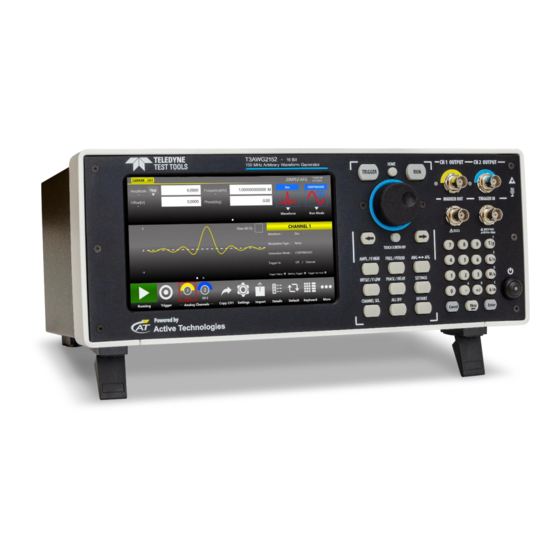
- Page 1 Operator’s Manual T3AWG2152 Simple AFG Rev. 1.0...
-
Page 2: Table Of Contents
ENVIRONMENTAL CONSIDERATIONS ........................8 ............................ 8 RODUCT LIFE ANDLING ..............................8 QUIPMENT ECYCLING PREFACE ................................9 ............................... 9 ACKAGE ONTENTS T3AWG2152 ........................9 ECOMMENDED CCESSORIES ............................9 ECHANICAL HARACTERISTICS ................................11 EY FEATURES INSTALLING YOUR INSTRUMENT.......................... 11 ............................11 PERATING EQUIREMENTS ............................ - Page 3 Numeric Keypad ..............................18 ................................19 ANEL Reference Clock Input Connector ........................20 Reference Clock Output Connector ........................20 Digital Output connector ............................ 20 INTRODUCTION ..............................21 ................................. 21 SIMPLE AFG SOFTWARE ............................22 AFG T UI ..............................22 IMPLE OUCH ............................
- Page 4 MAIN COMMAND BUTTON DESCRIPTION ......................50 ................................50 ETTINGS ................................51 ETTINGS ............................... 51 EMOTE ONTROL ............................. 53 HANNELS AND EVICE ETTING Channels Settings ..............................53 Device Settings ..............................55 Trigger In Settings ............................... 56 Marker Out Settings ............................57 ...............................
-
Page 5: General Safety Summary
Operator’s Manual Simple AFG Application General Safety Summary Review the following safety precautions to avoid injury and prevent damage to this product or any products connected to it. To avoid potential hazards, use this product only as specified. Only qualified personnel should perform service procedures. To Avoid Fire or Personal Injury Use Proper Power Cord Use only the power cord specified for this product and certified for the country of use. -
Page 6: Safety Requirements
Operator’s Manual Simple AFG Application Safety Requirements This section contains information and warnings that must be observed to keep the instrument operating in a correct and safe condition. You are required to follow generally accepted safety procedures in addition to the safety precautions specified in this section. Safety Symbols Where the following symbols appear on the instrument’s front or rear panels, or in this manual, they alert you to important safety considerations. - Page 7 Operator’s Manual Simple AFG Application CAUTION The CAUTION sign indicates a potential hazard. It calls attention to a procedure, practice or condition which, if not followed, could possibly cause damage to equipment. If a CAUTION is indicated, do not proceed until its conditions are fully understood and met. WARNING The WARNING sign indicates a potential hazard.
-
Page 8: Environmental Considerations
Operator’s Manual Simple AFG Application Environmental considerations Product End-of-life Handling Observe the following guidelines when recycling an instrument or component. Equipment Recycling Production of this equipment required the extraction and use of natural resources. The equipment may contain substances that could be harmful to the environment or human health if improperly handled at the product’s end of life. -
Page 9: Preface
The easiest touch screen display interface allows to create waveforms scenarios, only in few screen touches. The T3AWG2152 offers premium signal integrity thanks to the 16-bit resolution DAC. The output signal can reach up to 6Volts pk-pk into 50 Ohm single ended. The T3AWG2152can generate signals up to 150MHz. - Page 10 Operator’s Manual Simple AFG Application Overall Dimensions Height: 143 mm Width: 362 mm Depth: 258 mm...
-
Page 11: Key Features
Generator • Very long memory: up to 128MSample per channel • Mixed signal generation: 2 analog outputs + 8 digital outputs (T3AWG2152-D model only) • Simple touch screen user interface to create complex waveforms scenarios just in few screen touches •... -
Page 12: Environmental Requirements
Operator’s Manual Simple AFG Application The instrument is intended for indoor use and should be operated in a clean, dry, nonconductive environment. Occasionally a temporary conductivity that is caused by condensation must be expected. This location is a typical office/home environment. Temporary condensation occurs only when the product is out of service. -
Page 13: Cleaning
Operator’s Manual Simple AFG Application Cleaning To avoid personal injury, power off the instrument and disconnect it from line voltage WARNING. before performing any other following procedures. Inspect the arbitrary waveform generator as often as operating conditions require. To clean the exterior surface, perform the following steps: •... -
Page 14: Power The Instrument On And Off
Operator’s Manual Simple AFG Application Power the Instrument On and Off Power On • Insert the AC power cord into the power receptacle on the rear panel; • Use the front-panel power button to power on the instrument; • Wait until the system shows windows desktop; •... -
Page 15: Obtaining The Latest Version Releases
If your instrument has already installed another version of the Simple AFG application, you must first uninstall it. 1. Download the Simple AFGTouchUI setup package from Teledyne LeCroy website and decompress it to instrument’s local disk. 2. Double click on the “setup.exe” to start the installation. -
Page 16: Instrument Overview
Touch Screen The Touch screen functionalities and features are described in the Simple AFG Application paragraph. Analog Outputs The T3AWG2152 instrument has two analog output channels, each one is single-ended and the connector type is a standard BNC. Marker Output Connector . -
Page 17: Soft Keyboard And Rotary Knob
Operator’s Manual Simple AFG Application Soft keyboard and rotary knob Most of the buttons you use with Simple AFG application are virtual ones on the touchscreen, but a few physical buttons control basic functions, such as the setting of amplitude, offset, frequency, etc. A physical numeric keypad is available on the front-panel and it can be used instead of the virtual numeric pad. -
Page 18: Numeric Keypad
Operator’s Manual Simple AFG Application Button Description HOME If you are in a sub-menu page, use this button to return to the main page. TRIGGER Use this button to send an internal trigger to the instrument. Use this button to start and stop the signal generation. If the button is on and green the instrument is running while if it is off the instrument is stopped. -
Page 19: Rear Panel
Operator’s Manual Simple AFG Application When you select a parameter on the user interface, if you press a Unit Measure Range button it will automatically update the available range allowed for that parameter. Unit Measure Range Button Unit Measure Range Tera / pico Giga / nano Mega / micro... -
Page 20: Reference Clock Input Connector
Operator’s Manual Simple AFG Application Reference Clock Input Connector The T3AWG2152 instrument can use an external clock source to generate the sampling clock frequency. See “Auxiliary Channels” section form more information. The connector type is a SMA. Reference Clock Output Connector This connector outputs the internal 10MHz reference clock used to synthesize the DAC sampling clock. -
Page 21: Introduction
Operator’s Manual Simple AFG Application Introduction The T3AWG2152 instrument, when used in Arbitrary Function Generator mode, has two/four independent analog channels. Each channel can generate a predefined waveform, or a user defined waveform loaded from a file. Any characteristic parameter of the selected waveform can be modified at runtime. For example, if a pulse waveform is selected it is possible to define at runtime its amplitude, offset, frequency, duty cycle and the duration of leading and trailing edge. -
Page 22: Simple Afg Software
Operator’s Manual Simple AFG Application Simple AFG Software The T3AWG2152 instrument includes a 7” capacitive touch screen and an easy touch user interface based on a Microsoft Windows 10 platform. You can control instrument operations using one or all of the following entering methods: •... -
Page 23: User Interface Description
Operator’s Manual Simple AFG Application User Interface Description The Simple AFG software environment provides an easy access to all instrument functionalities and parameters. Waveform Parameters Area Channel Information Graph Area Command AFG user interface consists of four main elements: • Waveform Parameters Area: it contains all the waveform settings. - Page 24 Operator’s Manual Simple AFG Application If you use the Swipe left or right gesture on the Graph Area you can switch between the Output Channel 1 and Output Channel 2 page. If you use the Swipe left or right gesture on the Waveform Parameter Area you can switch the page between Carrier tab and the Secondary tab.
-
Page 25: Waveform Parameters Area
Operator’s Manual Simple AFG Application Waveform Parameters Area This section is composed by two tabs: the Carrier tab and the Secondary tab. • In the Carrier tab it is possible to define the Run Mode, of the Carrier Waveform and its parameters as explained in the relative chapter. - Page 26 Operator’s Manual Simple AFG Application 1. Parameter Name and Value: This area of the virtual keyboard displays the parameter name, value and unit of measure. 2. Numeric Keypad: this area contains the keys to edit the number that will be displayed in the area 1.
-
Page 27: Graph Area
Operator’s Manual Simple AFG Application Graph Area The graph area displays the Output channel waveform with a vertical legend that shows the minimum and maximum voltage levels and the offset. Note: When View All Ch. is checked the graph shows all channels graphs overlapped. The vertical scale is that of the selected channel. -
Page 28: Command Bar Area
Operator’s Manual Simple AFG Application Command Bar Area The command bar contains several touch buttons to control the instrument. Below a detailed description of this bar is provided. Please note that the position of the buttons described below may change due to instrument different model. - Page 29 Operator’s Manual Simple AFG Application Numeric Keyboard Button – Use this button to enable or disable the virtual numeric keyboard. More Button – Use this button to have access to other instrument features. These buttons are explained in the following table. More Button Menu Items Description Exit Button –...
- Page 30 Operator’s Manual Simple AFG Application About Button – Use this button to check the credits, the software, the firmware release number and the instrument serial number. Help Button – Use this button to open the User Manual.
-
Page 31: Input / Output Channels
Operator’s Manual Simple AFG Application Input / Output Channels The T3AWG2152 instrument has two independent analog channels. Each channel is a single-ended output and it is provided on a BNC connector located on the front instrument panel (CH 1 OUTPUT, CH 2 OUTPUT). - Page 32 Operator’s Manual Simple AFG Application The amplitude can be represented in three different formats that can be selected by opening the menu beside the amplitude label: • Vpp (Peak to Peak Voltage): it is the difference between the highest and lowest level of the waveform.
- Page 33 Operator’s Manual Simple AFG Application Low Level [V] It defines the minimum level of the waveform expressed in Volts These parameters are available for all function excepts the DC level that is identified only by the Offset parameter.
-
Page 34: Main Channels Horizontal Parameter
Operator’s Manual Simple AFG Application Main Channels Horizontal parameter The horizontal parameters control the frequency, the phase and the shape of the waveform. The set of available parameters depends on the selected waveform. Frequency [Hz] / Period [s] This parameter defines the frequency or the period of the generated waveform. This parameter is available for all the functions except DC Level and Noise. - Page 35 Operator’s Manual Simple AFG Application...
-
Page 36: Auxiliary Channels
Operator’s Manual Simple AFG Application Auxiliary Channels Marker Out The Marker Out generates a digital pulse synchronous with the waveform or with the modulating function depending on the Run Mode. To set the Marker Out parameters refer to the Channel Settings. Marker Out Specification Value Connector 1 BNC on the Front Panel... -
Page 37: Reference Clock Input
Operator’s Manual Simple AFG Application Reference Clock Input The T3AWG2152instrument can use an external clock source to generate the sampling clock frequency. This feature allows to synchronize the generator with an external clock. The connector type is a SMA. When the “Clock Source” is set on “External” in the “Device Settings” page, the internal clock synthesizer uses the signal from “Reference Clock Input”... -
Page 38: Predefined Waveforms
Operator’s Manual Simple AFG Application Predefined Waveforms The Simple AFG application provides 13 predefined functions each of them described by its own set of parameters. It is also available the Arbitrary waveform that allow to load a waveform from a file or from remote. - Page 39 Operator’s Manual Simple AFG Application Waveform Frequency Range Parameters PWM Sweep Burst PSK, Square Amplitude, Offset, √ √ √ 1 uHz÷60 MHz ≤ 6Vpp Frequency, Phase Ramp Amplitude, Offset, √ √ √ 1 uHz÷5 MHz ≤ 6Vpp Frequency, Phase, Symmetry Pulse Amplitude, Offset, Frequency, Phase, Duty...
- Page 40 Operator’s Manual Simple AFG Application Waveform Frequency Range Parameters PWM Sweep Burst PSK, Gaussian Amplitude, Offset, √ √ √ 1 uHz÷10 MHz ≤ 6Vpp Frequency, Phase Lorentz Amplitude, Offset, √ √ √ 1 uHz÷10 MHz ≤ 6Vpp Frequency, Phase Exponential Rise Amplitude, Offset, √...
- Page 41 Operator’s Manual Simple AFG Application You can assign the “Arbitrary” waveform using the “Import” button of the command bar. For more information refer to the “Import from File” section. By default, the “Arbitrary” waveform is a cosine function. Note: When Arbitrary waveform is selected the amplitude and offset of the original waveform are lost because the waveform in normalized.
-
Page 42: Run Mode
Operator’s Manual Simple AFG Application Run Mode On the Carrier tab pressing the “Run Mode” button a menu opens showing all possible choices for the Run Mode. If “Modulation”, “Sweep” or “Burst” is selected the software moves directly on the secondary tab that takes the name of the selected Run Mode. -
Page 43: Modulation
Operator’s Manual Simple AFG Application Marker out (blue, top) synchronous with the analog signal (red, bottom) Modulation In this Run Mode, it is possible to modulate a carrier waveform with a modulation law. All waveforms except Noise and DC level support the Modulation Run Mode. Touching the “Type”... -
Page 44: Marker Out Behaviour In Modulation Run Mode
Operator’s Manual Simple AFG Application Touching the “Shape” button the modulation type menu opens. The possibility to choose the shape is only available for AM, FM, PM and PWM modulations. The modulation Shapes (when available) can be: • Sine • Square •... -
Page 45: Modulation General Parameter
Operator’s Manual Simple AFG Application Modulation General Parameter • Frequency [Hz]: it defines the modulating frequency. It can vary between 500uHz and 48MHz. Modulation Types and associated parameters • Amplitude Modulation (AM): the amplitude of the carrier waveform is modulated following the modulating shape. -
Page 46: Sweep
Operator’s Manual Simple AFG Application Where ε is a small margin to avoid that the duty cycle reaches the 0 % or the 100 % and the factor “0.8” take in account that the edges are defined as 10-90%. Sweep The Sweep mode varies the waveform frequency following a law that can be Linear, Logarithm, Upstair or User Defined. -
Page 47: Sweep Mode
Operator’s Manual Simple AFG Application Sweep Mode Touching the Sweep Mode button, a menu opens that gives the possibility to choose a sweep profile among the following: • Linear: the frequency increases and decreases linearly. • Logarithm: the frequency increases and decreases following a logarithmic function. •... -
Page 48: Burst
Operator’s Manual Simple AFG Application Burst In Burst mode a waveform is repeated a predefined number of times or until the Trigger signal is at High Level depending on the selected Burst Type. This Run Mode is available for all waveforms except the DC level. - Page 49 Operator’s Manual Simple AFG Application • Inf-Cycles: this mode is similar to the previous one, but after the Trigger the generation starts until the Run/Stop Button is pressed. • Gated: the waveform is generated only when the Trigger is “true”. When the trigger returns to “false”...
-
Page 50: Main Command Button Description
Operator’s Manual Simple AFG Application Main Command Button Description Save Settings The button “Save Settings” in the “More” menu allows to save the current instrument settings called “memory”. In the relative dialogue box, you can save a new memory entry or overwrite an existing one. -
Page 51: Load Settings
Operator’s Manual Simple AFG Application Load Settings Touching the “Load Settings” button in the “More” menu, a page will open showing the list of all the saved memories. Selecting a memory entry the current instrument settings will be immediately updated with those of the memory entry. The buttons have the same functions they have in the “Save Settings”... - Page 52 Operator’s Manual Simple AFG Application In the top of the page the Host Name and the IP Address of the instrument are shown. The slider on the right side of the page allows to enable or disable the SCPI server. By default it is enabled.
-
Page 53: Channels And Device Setting
Operator’s Manual Simple AFG Application Channels and Device Setting Press this button to open the settings page composed by three tabs, one for each Channel and one for the Device. You can swipe left or right to switch among the tabs. Touching a channel button or pressing the “CHANNEL SEL.”... - Page 54 Operator’s Manual Simple AFG Application Channel Setting Description Initial Delay Set the Initial Delay of the selected channel. The delay range is 0s to 14 s. Load [Ohm] The instrument applies the appropriate scaling to the output waveform to get the right amplitude on the defined Load expressed in Ohm. The impedance range is 1 Ohm to 1MOhm.
-
Page 55: Device Settings
Operator’s Manual Simple AFG Application Device Settings The “Device Settings” page contains the general setting of the instrument, such as the clock source and the Marker Out setting. Touching the “Settings” button in the menu bar or the “SETTINGS” button on the keyboard the channel settings page open. -
Page 56: Trigger In Settings
Operator’s Manual Simple AFG Application Trigger In Settings The Trigger In settings parameters are located in the Device Setting page. These parameters are shared by each channel of the instrument. Trigger In Setting Description Source Button: The Trigger event is provided to the instrument by the Trigger button on the keyboard or Trigger button on the menu bar or from a Remote Command. -
Page 57: Marker Out Settings
Operator’s Manual Simple AFG Application Marker Out Settings The Marker Out settings parameters are located in the Device Setting page. The MARKER OUT BNC connector is shared by each channel of the instrument but it’s possible to link the marker signal coming out of it to a predetermined one. -
Page 58: Import From File
Operator’s Manual Simple AFG Application Import from File The Import page allows to load a waveform from a file and assign it to the Carrier waveform or to the Modulation profile or to the Sweep profile. This page opens by touching the Import button Once the waveform has been imported it will be available by choosing “Arbitrary”... - Page 59 Operator’s Manual Simple AFG Application Import File Specifications Description Accepted Formats .txt (Tab Separated text), .csv(Comma Separated Value), .trc (LeCroy Digital oscilloscope) Length Range Between 2 and 16384 samples. The instrument memory is limited at 16 k sample (16384) for each arbitrary waveform. If a longer waveform is imported it will be resampled to match the maximum length.
- Page 60 Operator’s Manual Simple AFG Application • Import: opens the file system browser to search and load a waveform. The loaded waveform is added to the Waveform List. • Carrier: assigns the selected waveform to the “Arbitrary” Carrier of the current channel. •...
-
Page 61: Channel Coupling
Operator’s Manual Simple AFG Application Channel Coupling In electronics design and testing, you sometimes want to have two synchronized clock signals that are related by a frequency ratio; one clock needs to maintain a certain frequency ratio with the other clock. Or perhaps, you want to simulate an amplifier with an offset;... - Page 62 Operator’s Manual Simple AFG Application • Swipe up or down to select which channel to couple to the Channel 1. • ON/OFF button: enables or disables the channel coupling. • Reset: resets the Ratio and Offset parameters to their default values (1 and 0). •...
- Page 63 Operator’s Manual Simple AFG Application Now if you set the Offset to 1MHz the coupling equation will be: CH2 Frequency = Channel1 Frequency*2.5 + 1MHz and changing channel 1’s frequency will change channel 2’s frequency to maintain the specified ratio and offset in real time: if you set Channel 1 frequency to 1MHz you will get 3.5MHz on channel 2.
-
Page 64: Certifications
Operator’s Manual Simple AFG Application Certifications Teledyne LeCroy certifies compliance to the following standards as of the time of publication. Please see the EC Declaration of Conformity document shipped with your product for current certifications. EMC Compliance EC DECLARATION OF CONFORMITY - EMC The instrument meets intent of EC Directive 2014/30/EU for Electromagnetic Compatibility. -
Page 65: Environmental Compliance
Operator’s Manual Simple AFG Application • Mains Supply Connector: Overvoltage Category II, instrument intended to be supplied from the building wiring at utilization points (socket outlets and similar). • Measuring Circuit Terminals: No rated measurement category. Terminals not intended to be connected directly to the mains supply.
Need help?
Do you have a question about the T3AWG2152 and is the answer not in the manual?
Questions and answers