Table of Contents
Advertisement
OPERATING INSTRUCTIONS FOR
Model 3110
Portable Trace Oxygen Analyzer
P/N M77970
10/16/2005
ECO:
DANGER
Toxic gases and or flammable liquids may be present in this monitoring system.
Personal protective equipment may be required when servicing this instrument.
Hazardous voltages exist on certain components internally which may persist
for a time even after the power is turned off and disconnected.
Only authorized personnel should conduct maintenance and/or servicing.
Before conducting any maintenance or servicing, consult with authorized
supervisor/manager.
Copyright © 2005 Teledyne Analytical Instruments
Teledyne Analytical Instruments
Advertisement
Table of Contents

Related Manuals for Teledyne 3110


Summary of Contents for Teledyne 3110
- Page 1 Hazardous voltages exist on certain components internally which may persist for a time even after the power is turned off and disconnected. Only authorized personnel should conduct maintenance and/or servicing. Before conducting any maintenance or servicing, consult with authorized supervisor/manager. Copyright © 2005 Teledyne Analytical Instruments Teledyne Analytical Instruments...
- Page 2 Teledyne Instruments / Analytical Instruments, 16830 Chestnut Street, City of Industry, CA 91748.
- Page 3 Portable Trace Oxygen Analyzer Specific Model Information Instrument Serial Number: _______________________ Teledyne Analytical Instruments...
- Page 4 Model 3110 Safety Messages Your safety and the safety of others is very important. We have provided many important safety messages in this manual. Please read these messages carefully. A safety message alerts you to potential hazards that could hurt you or others.
- Page 5 Manuals do get lost. Additional manuals can be obtained from TAI at the address given in the Appendix. Some of our manuals are available in electronic form via the Internet. Please visit our website at: www.teledyne-ai.com. Teledyne Analytical Instruments...
-
Page 6: Table Of Contents
Model 3110 Table of Contents List of Figures................viii Introduction ................10 1.1 Introduction 1.2 Features 1.3 Method of Analysis 1.4 Micro-Fuel Cell 1.4.1 Cell Warranty 1.5 Accuracy and Response 1.6 Signal Output 1.7 Compact Packaging Installation .................. 17 2.1 Charging the Batteries 2.2 Gas Connections... - Page 7 4.1 Routine Maintenance 4.2 Opening the Instrument Case 4.3 Replacing the Battery 4.4 Battery Power Supply Service 4.5 Cell Replacement 4.6 Cell Warranty 4.7 Temperature Compensation 4.8 Leak Testing Appendix ..................48 A.1 Specifications A.2 Spare Parts List Index ....................50 Teledyne Analytical Instruments...
-
Page 8: List Of Figures
List of Figures Figure 2-1: Model 3110 Rear Panel ..........18 Figure 3-1: Front Panel Keys ............25 Figure 3-2: Available Menus and Their Sequence ......26 Figure 4-1: Battery Charger Port on the Model 3110 ....42 Teledyne Analytical Instruments viii... - Page 9 Since the use of this instrument is beyond the control of Teledyne Analytical Instruments, referred as TAI, no responsibility by TAI, its affiliates, and agents for damage or injury from misuse or neglect of this equipment is implied or assumed.
-
Page 10: Introduction
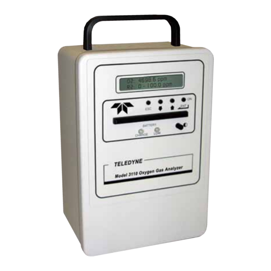
The Model 3110 incorporates a large standard feature list designed for versatile, accurate oxygen analysis for a wide range of applications. Figure 1-1 shows the standard Model 3110 Portable Trace Oxygen Analyzer. -
Page 11: Features
Portable Trace Oxygen Analyzer Introduction WARNING Though the 3110 can be applied to monitor percent oxygen, doing so will lead to more frequent sensor replacement requirements. Figure 1-1: Model 3110 Portable Trace Oxygen Analyzer 1.2 Features This instrument is designed to be a versatile analytical instrument and to perform reliably and accurately in analyzing oxygen concentrations in gas mixtures from the ppm level through 25% oxygen. - Page 12 • Real-time Clock: This feature allows the Model 3110 to date and time stamp the data set recorded on the data logger. It uses a 24 hour clock.
-
Page 13: Method Of Analysis
1.4.1 Cell Warranty The Class B2-C, A2C, B2C-XL and Insta Trace micro-fuel cells can be used in the Model 3110 and are warranted for six (6) months from the date of shipment. With regard to spare cells, service time starts when the cell is removed from its shipping package. -
Page 14: Accuracy And Response
±1 ppm, whichever is greater, at constant temperature. With a sample flow rate of 1 SCFH, a 90% response can be realized in 60 seconds. The response time on the 3110 is limited by the filter setting. 1.6 Signal Output... - Page 15 Portable Trace Oxygen Analyzer Introduction affect meter accuracy, the Model 3110 can be used in any position without interference. Teledyne Analytical Instruments...
- Page 16 Introduction Model 3110 Intentionally left blank. Teledyne Analytical Instruments...
-
Page 17: Installation
The instrument should not be left on the charger for longer than 20 hours nor should the charger be left attached to the instrument when the unit is not charging. The Model 3110 cannot be operated while the battery charger is attached. -
Page 18: Gas Connections
LED due to the power drain and low battery condition. At this point the unit should be removed from service and the batteries recharged. Figure 2-1: Model 3110 Rear Panel 2.2 Gas Connections The customer must provide a means of controlling the pressure and flow rate of the sample and zero gas. - Page 19 Do not place any valves or restrictions on the vent line except as noted above for atmospheric pressure sampling when using a downstream pump. Doing so would increase the sensor operating pressure and result in inaccurate analysis. Teledyne Analytical Instruments...
-
Page 20: Sensor Installation
2.3 Sensor Installation The Model 3110's trace sensor requires that the instrument lines be immediately purged with zero gas after installing the cell. 2.3.1 Installing a Trace Sensor Prior to installing the trace sensor, make sure the analyzer is ready to purge with zero gas. -
Page 21: Calibration
120-135 ppm oxygen in nitrogen. 2.4.1 Calibration Procedure for Trace Analysis To calibrate the Model 3110, the instrument must be fitted with a trace sensor. The instrument must also be purged overnight using a zero gas (a pure gas with no oxygen, typically O free N ) before calibrating. -
Page 22: Bleeding The Regulator And Purging The Gas Line
Installation Model 3110 2.4.2 Bleeding the Regulator and Purging the Gas Line When using bottled gas (gas cylinder) as a calibration gas for trace analysis applications, the regulator and sample lines must be bled to remove traces of trapped air. Otherwise air that is trapped in the lines especially between the regulator and cylinder will result in a lengthening of the calibration time. -
Page 23: External Signal
0.1 V would represent 1 ppm, 0.2V would be 2 ppm; 0.3V would be 3 ppm etc. This output signal, when installed, is accessible from the rear panel. The output signal has an input impedance of 100Ω. Teledyne Analytical Instruments... -
Page 24: Operation
3.1 Front Panel Interface The Model 3110 is controlled from the keys on the front panel and is shown in Figure 3-1. These keys are also used to setup the instrument for your application. The keys are: •... -
Page 25: Escape Key
The values will revert to the last value saved for that entry. 3.1.3 UP/DOWN Keys The UP/DOWN keys are used to: • Navigate from one screen to another • Toggle between multiple options within a menu Teledyne Analytical Instruments... -
Page 26: Operation And Setup Screens And Menus
• Increment or decrement a value 3.2 Operation and Setup Screens and Menus The Model 3110 operation and setup functions are arranged in a set of 15 menus. All but the POWER ON screen are accessible via the UP/DOWN keys. Figure 3-2 shows the available menus and the sequence of screens when scrolling. -
Page 27: Power On Screen
To change the currently set date: 1. Press ENTER to enter the date setup function. Note the navigation arrows that appear on the left and right sides of the display change from UP/DOWN to pointing LEFT/RIGHT. Teledyne Analytical Instruments... -
Page 28: Time Screen
Operation Model 3110 2. Use the UP/DOWN keys to alter the month. Then press ENTER. The cursor will move over to the next editable field. 3. Use the UP/DOWN keys to alter the day. Then press ENTER. The cursor will move over to the next editable field. -
Page 29: Standard Alarm Screen
The next four screens determine the characteristics of the alarm: whether it is on or off, failsafe or non-failsafe, HI or LOW activating, or latching or non-latching in its operation. From the ALARM ENABLE screen you can set whether the alarm is on or off. Teledyne Analytical Instruments... -
Page 30: Fs Alarm Screen
3. Press ENTER again to save the alarm status and return to the FS ALARM screen. 3.2.8 HI-LOW ALARM Screen The HI-LO screen indicates how the Model 3110 alarm functions. The alarm on the Model 3110 can be set up as either a HI alarm or LO Teledyne Analytical Instruments... -
Page 31: Ltch Alarm Screen
HI-LO ALARM screen. 3.2.9 LTCH ALARM Screen The alarm on the Model 3110 can be set up as latching or non- latching. A latching alarm, once triggered, will remain in alarm status until recognized and reset. Even if the concentration changes back to a non-alarm concentration, a latched alarm will remain in alarm status. -
Page 32: Range 1 Screen
(It can be disabled) 3.2.10 RANGE 1 Screen The Model 3110 is capable of using two user defined ranges in the auto-ranging mode however, if the instrument is used in manual mode (see Section 3.2.12), only RANGE 1 is recognized. -
Page 33: Range Screen
Then press ENTER to enter the setup screen. 2. Use the UP/DOWN keys to toggle between MAN and AUTO for the range mode. Press ENTER to accept the displayed mode. 3. Press ENTER again to return to the RANGE screen. Teledyne Analytical Instruments... -
Page 34: Span Value Screen
SPAN VALUE screen. 3.2.14 SPAN Screen This screen is used to perform a span calibration on the Model 3110. The appropriate span value must have already been input to the instrument. See Section 3.2.13 for entering a span value into the analyzer. -
Page 35: Filter Screen
3.2.15 Filter Screen The 3110 includes user adjustable filter. The filter has settings 1- 10. Setting 1 is the least amount of filtering and 10 is the highest level of damping. The filter is used to reduce the noise level of the O readings. -
Page 36: Log Intv Screen
Operation Model 3110 To use this feature: 1. Use the UP/DOWN keys to navigate to the FILTER screen. Then press ENTER to enter the setup screen. 2. Use the ENT/ON key to change the filter to the active mode. The arrows will point left and right and the filter setting will blink. -
Page 37: Log Transmit Screen
PC. The RS-232 port accepts a standard data cable with a DB-9 connector. The computer must be able to accept data from a RS-232 source with the following characteristics: 9600 baud 8 bit data no parity Teledyne Analytical Instruments... -
Page 38: Power Down Screen
Operation Model 3110 1 stop bit no flow control Refer to your computer manual for details on how to setup the optional RS-232 communications port on your computer. To download a data log: 1. Use the UP/DOWN keys to navigate to the LOG TRANSMIT screen. - Page 39 Portable Trace Oxygen Analyzer Operation 1. Use the UP/DOWN keys to navigate to the POWER DOWN screen. Then press ENTER. 2. Press ENTER again to turn the instrument OFF. In a few seconds the analyzer will turn off. Teledyne Analytical Instruments...
-
Page 40: Maintenance & Troubleshooting
Maintenance Model 3110 Maintenance & Troubleshooting 4.1 Routine Maintenance Other than replacing the sensor and cell holder O-ring, there are no user-serviceable components within the instrument housing. Routine maintenance consists of wiping down the instrument case, cleaning the screen and checking for leaks. -
Page 41: Battery Power Supply Service
4.4 Battery Power Supply Service The Model 3110 is designed to be intrinsically safe, and is designed for use only when not connected to the AC power line. TAI suggests that an overnight recharge be performed every few days for continuous use. -
Page 42: Cell Replacement
Maintenance Model 3110 Figure 4-1: Battery Charger Port on the Model 3110 4.5 Cell Replacement The characteristics of the micro-fuel cell are similar to those of a NiCad battery in that both provide an almost constant output through their useful life, and then fall off sharply towards zero at the end. If the sample being analyzed has a low oxygen concentration, cell failure will probably be indicated by the inability to properly calibrate the analyzer. -
Page 43: Cell Warranty
4.6 Cell Warranty The Class B-2C, A-2C, B-2CXL and Insta Trace micro-fuel cells used in the Model 3110 are warranted for six (6) months of service. With regard to spare cells, service time starts when the cell is removed from its oxygen barrier packaging. The customer should stock only one spare cell per instrument at a time. -
Page 44: Temperature Compensation
Maintenance Model 3110 cell performance will not be affected. On the following page is a graph showing the effects of CO on cell life. WARNING: EVIDENCE OF DAMAGE DUE TO TAMPERING OR MISHANDLING WILL RENDER THE CELL WARRANTY NULL AND VOID. - Page 45 6. The CO effect on B-2 cells is independent of the O level. Usage in contributes significantly to cell life reduction and thus affects cell warranty. Figure 4-2: Effects of CO2 on B-2 Cell Life Teledyne Analytical Instruments...
-
Page 46: Leak Testing
Maintenance Model 3110 4.8 Leak Testing WARNING: IF A LEAK IS SUSPECTED IN THE UNIT, DO NOT ATTEMPT TO TIGHTEN THE QUICK DISCONNECT FITTINGS. THE FITTINGS ARE POTTED IN EPOXY AND TIGHTENING THEM WILL BREAK THE SEAL. To check for leaks, TAI recommends one of the following... - Page 47 Portable Trace Oxygen Analyzer Maintenance Intentionally left blank. Teledyne Analytical Instruments...
-
Page 48: Appendix
Appendix Model 3110 Appendix A.1 Specifications TAI Sales Order Number: Instrument Serial Number: Micro-fuel Cell Class: B-2, A-2C, B-2CXL, Insta Trans Ranges of Analysis: 2 user defined ranges* Accuracy: ±2% of scale or ±1 PPM (whichever is greater) at constant temperature;... -
Page 49: Spare Parts List
Orders should be sent to: TELEDYNE ANALYTICAL INSTRUMENTS 16830 Chestnut Street City of Industry, California 91748 USA Phone: (626) 934-1500 FAX: (626) 934-1651 or your local representative www.teledyne-ai.com | email: ask_tai@teledyne.com Teledyne Analytical Instruments... -
Page 50: Index
Appendix Model 3110 Index A2C cell, 43 clock, 12 AC adapter. See charge adapter CO2 component, 43 AC charger port, 41 combustible gas warning, ix accuracy, 14, 48 company address, 49 alarm, 29 contact plate, 43 enable/disable, 29 continuous operation, 18, 41... - Page 51 43 quick disconnect button, 19 sulfur dioxide, 13 quick disconnect fitting, 10, 13, 19 technician symbol, iv RAM, 11 Teflon membrane, 43 range. See analysis range temperature coefficient, 44 RANGE 1 screen, 32 temperature compensation, 13, 44 Teledyne Analytical Instruments...
- Page 52 Appendix Model 3110 throttle valve, 18 vent line restriction, 19 time format, 28 warning sign, iv TIME screen, 28 warranty, ii time stamping, 28 warranty claim, 14 trace analysis application, 19 website address, v trapped air, 20, 21 weight, 48...
Need help?
Do you have a question about the 3110 and is the answer not in the manual?
Questions and answers