Table of Contents
Advertisement
Quick Links
Trace Oxygen Analyzer
OPERATING INSTRUCTIONS FOR
Model
Ultra Trace 3000
Oxygen Analyzer
DANGER
HIGHLY TOXIC AND OR FLAMMABLE LIQUIDS OR GASES MAY BE PRESENT IN THIS MONITORING
SYSTEM.
PERSONAL PROTECTIVE EQUIPMENT MAY BE REQUIRED WHEN SERVICING THIS SYSTEM.
HAZARDOUS VOLTAGES EXIST ON CERTAIN COMPONENTS INTERNALLY WHICH MAY PERSIST
FOR A TIME EVEN AFTER THE POWER IS TURNED OFF AND DISCONNECTED.
P/N M70946
12/10/99
ONLY AUTHORIZED PERSONNEL SHOULD CONDUCT MAINTENANCE AND/OR SERVICING. BEFORE
CONDUCTING ANY MAINTENANCE OR SERVICING CONSULT WITH AUTHORIZED SUPERVISOR/
ECO # 99-0483
MANAGER.
Teledyne Analytical Instruments
i
Advertisement
Table of Contents

Related Manuals for Teledyne Ultra Trace 3000


Summary of Contents for Teledyne Ultra Trace 3000
- Page 1 Trace Oxygen Analyzer OPERATING INSTRUCTIONS FOR Model Ultra Trace 3000 Oxygen Analyzer DANGER HIGHLY TOXIC AND OR FLAMMABLE LIQUIDS OR GASES MAY BE PRESENT IN THIS MONITORING SYSTEM. PERSONAL PROTECTIVE EQUIPMENT MAY BE REQUIRED WHEN SERVICING THIS SYSTEM. HAZARDOUS VOLTAGES EXIST ON CERTAIN COMPONENTS INTERNALLY WHICH MAY PERSIST FOR A TIME EVEN AFTER THE POWER IS TURNED OFF AND DISCONNECTED.
- Page 2 Any safeguards required such as locks, labels, or redun- dancy, must be provided by the user or specifically requested of Teledyne at the time the order is placed.
- Page 3 Ultra Trace 3000-V: Instrument configured for Vacuum Service 19" Rack Mnt: The 19" Relay Rack Mount units are available with one Ultra Trace 3000 series analyzers installed in a standard 19" panel and ready to mount in a standard rack.
-
Page 4: Table Of Contents
4.2 Using the Data Entry and Function Buttons ....4-2 4.3 The System Function ............. 4-3 4.3.1 Tracking the O Readings during CAl & Alarm ..4-4 4.3.2 Setting up an Auto-Cal ........... 4-5 4.3.3 Password Protection ..........4-6 4.3.3.1 Entering the Password ........4-7 Teledyne Analytical Instruments... - Page 5 A-1 Model Ultra Tace 3000 Specifications ......A-1 A-2 Recommended 2-Year Spare Parts List ......A-3 A-3 Drawing List ..............A-4 A-4 19-Inch Relay Rack Panel Mount ........A-4 A-5 Application Notes on Pressures and Flow ..... A-5 Teledyne Analytical Instruments...
- Page 6 Since the use of this instrument is beyond the control of Teledyne, no responsibility by Teledyne, its affiliates, and agents for damage or injury from misuse or neglect of this equipment is implied or assumed.
-
Page 7: Introduction
Model Ultra Trace 3000 General Purpose flush-panel and/or rack-mount units only. These units are for indoor use in a nonhazardous environment. Typical Applications A few typical applications of the Model Ultra Trace 3000 are: • Monitoring inert gas blanketing •... -
Page 8: Model Designations
Isolated 4–20 mA dc) and two for range identification. • Convenient and versatile, steel, flush-panel or rack-mountable case with slide-out electronics drawer. Model Designations Ultra Trace 3000: Standard model for sample under pressure Ultra Trace 3000-V: Instrument configured for Vacuum Service Teledyne Analytical Instruments... -
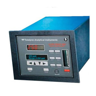
Page 9: Front Panel (Operator Interface)
Introduction 1 Front Panel (Operator Interface) The standard Ultra Trace 3000 is housed in a rugged metal case with all controls and displays accessible from the front panel. See Figure 1-1. The front panel has thirteen buttons for operating the analyzer, a digital meter, an alphanumeric display, and a window for viewing the sample flowmeter. - Page 10 1 Introduction Model Ultra Trace 3000 • Alarms Set the alarm setpoints and attributes. • Range Set up the 3 user definable ranges for the instrument. Data Entry Keys: Six touch-sensitive membrane switches are used to input data to the instrument via the alphanumeric VFD display: •...
-
Page 11: Rear Panel (Equipment Interface)
3 Installation. T el e d y n e A n a ly tic a l I n str u m e n ts Figure 1-2: Model Ultra Trace 3000 Rear Panel •... - Page 12 Note: If you require highly accurate Auto-Cal timing, use external Auto-Cal control where possible. The internal clock in the Model Ultra Trace 3000 is accurate to 2-3 %. Accordingly, internally scheduled calibrations can vary 2-3 % per day. Teledyne Analytical Instruments...
-
Page 13: Operational Theory
Micro-Fuel Cell Sensor 2.2.1 Principles of Operation The oxygen sensor used in the Model Ultra Trace 3000 series is a Micro-fuel Cell, Model B-2CXL designed and manufactured by Analytical Instruments. It is a sealed plastic disposable electrochemical transducer. -
Page 14: Anatomy Of A Micro-Fuel Cell
2 Operational Theory Model Ultra Trace 3000 comes from outside the device as a constituent of the sample gas being analyzed. The Micro-Fuel Cell is therefore a hybrid between a battery and a true fuel cell. (All of the reactants are stored externally in a true fuel cell.) 2.2.2 Anatomy of a Micro-Fuel Cell... -
Page 15: Electrochemical Reactions
It is measured and used to determine the oxygen concentration in the gas mixture. The overall reaction for the fuel cell is the SUM of the half reactions above, or: 2Pb + O 2PbO Teledyne Analytical Instruments... -
Page 16: The Effect Of Pressure
2.2.6 TEC Cooling System Ultra Trace 3000 analyzers include an advance Thermal Electric Cooler (TEC) system. This system enhances the performance of the Micro-fuel Cell by cooling it and regulating its operating temperature. The TEC system includes a TEC module, a temperature control PCB, a separate power supply, a thermistor, and a special insulated cellblock. - Page 17 PCB uses a thermistor to monitor the temperature of the of cell block. Power for the fan, and the temperature controller PCB is supplied by a separate 12VDC power supply. Figure 2-3. Characteristic Input/Output Curve for a Micro-Fuel Cell Teledyne Analytical Instruments...
-
Page 18: Sample System
Depending on the mode of operation either sample or calibration gas is delivered. The Model Ultra Trace 3000 sample system is designed and fabricated to ensure that the oxygen concentration of the gas is not altered as it travels through the sample system. - Page 19 Ultra Trace Oxygen Analyzer Operational Theory 2 Figure 2-5: Flow Diagram-Sample Under Pressure -Standard Model Ultra Trace 3000 -Do not exceed 10" Hg Vacuum- Figure 2-5-1: Flow Diagram-Sample at Zero Pressure -Model Ultra Trace 3000-V Teledyne Analytical Instruments...
-
Page 20: Electronics And Signal Processing
Electronics and Signal Processing The Model Ultra Trace 3000 Oxygen Analyzer uses an 8031 microcon- troller with 32 kB of RAM and 128 kB of ROM to control all signal pro- cessing, input/output, and display functions for the analyzer. System power is supplied from a universal power supply module designed to be compatible with any international power source. - Page 21 Temperature Controller System Micro- Failure Processor Alarm Processing Displays Self Test Signal Concentration D to A 0-1 V Converter 4-20 mA Range 0-1 V 4-20 mA Figure 2-7: Block Diagram of the Model Ultra Trace 3000 Electronics Teledyne Analytical Instruments...
- Page 22 2 Operational Theory Model Ultra Trace 3000 In the presence of oxygen the cell generates a current. A current to voltage amplifier converts this current to a voltage, which is further amplified in the second stage amplifier. The output from the second stage amplifier is sent to an 18 bit analog to digital converter controlled by the microprocessor.
-
Page 23: Installation
Mounting the Analyzer The Model Ultra Trace 3000 is for indoor use in a general purpose area. It is NOT for hazardous environments of any type. The standard model is designed for flush panel mounting. Figure 3-1 is an illustration of the Ultra Trace 3000 standard front panel and mounting bezel. - Page 24 Standby Enter 10” Figure 3-1: Front Panel of the Model Ultra Trace 3000 All operator controls are mounted on the control panel, which is hinged on the left edge and doubles as the door that provides access to the sensor and cell block inside the instrument.
-
Page 25: Rear Panel Connections
Ultra Trace Oxygen Analyzer Installation 3 Rear Panel Connections Figure 3-3 shows the Model Ultra Trace 3000 rear panel. There are ports for gas inlet and outlet, power, communication, and both digital and analog concentration output. Te le d y n e A n aly tic a l In s tru m e n ts Figure 3-3: Rear Panel of the Model Ultra Trace 3000 3.3.1 Gas Connections... -
Page 26: Electrical Connections
3 Installation Model Ultra Trace 3000 If greater sample flow is required for improved response time, install a bypass in the sampling system upstream of the analyzer input. VACUUM SERVICE: If the sample pressure is at atmospheric or very low pressure, the instrument must be ordered with the vacuum service option. - Page 27 – % Range, 0-1 V dc, negative ground Alarm Relays: The nine alarm-circuit connector pins connect to the internal alarm relay contacts. Each set of three pins provides one set of Form C relay contacts. Each relay has both normally open and normally closed Teledyne Analytical Instruments...
- Page 28 3 Installation Model Ultra Trace 3000 contact connections. The contact connections are shown in Table 3-2. They are capable of switching up to 3 amperes at 250 V ac into a resistive load. The connectors are: Threshold Alarm 1: • Can be configured as high (actuates when concen- tration is above threshold), or low (actuates when concentration is below threshold).
- Page 29 Cal Contact Remote Calibration Protocol: To properly time the Digital Remote Cal Inputs to the Model Ultra Trace 3000 Analyzer, the customer's controller must monitor the Cal Relay Contact. When the contact is OPEN, the analyzer is analyzing, the Remote Cal Inputs are being polled, and a zero or span command can be sent.
- Page 30 At this printing, this port is not yet functional. It is to be used for future options to the instrument. Pins 13 (+) and 29 (–). Remote Valve Connections: The Ultra Trace 3000 is a single-chassis instrument, which has no Remote Valve Unit. Instead, the Remote Valve connections are used as a method for directly controlling external sample/ zero/span gas valves.
- Page 31 In addition, each individual line has a series FET with a nominal ON resistance of 5 ohms (9 ohms worst case). This can limit the obtainable voltage, depending on the load impedance applied. See Figure 3-6. Figure 3-6: FET Series Resistance Teledyne Analytical Instruments...
-
Page 32: Installing The Micro-Fuel Cell
3 Installation Model Ultra Trace 3000 Installing the Micro-Fuel Cell The Micro-Fuel Cell, Model B-2CXL is not installed in the cell block when the instrument is shipped. Install it before the analyzer is placed in service. The Micro-Fuel cell is located inside the stainless steel cell block behind the front panel (see Figure 3-8). - Page 33 Ultra Trace Oxygen Analyzer Installation 3 COLLAR CELL BLOCK SENSOR O-RING CELL HOLDER Figure 3-8: Installing the Micro-Fuel Cell 3-11 Teledyne Analytical Instruments...
- Page 34 3 Installation Model Ultra Trace 3000 IMPORTANT: ` In the event of loss of flow through the analyzer, if the vent is vented to a location of high oxygen content, oxygen will back diffuse through the vent line and in most cases quickly saturate the cell with...
-
Page 35: Operation
• Set alarm setpoints, and modes of alarm operation (latching, failsafe, etc). Before you configure your Ultra Trace 3000, these default values are in effect: Ranges: LO = 250ppb ppm, MED = 1 ppm, HI = 10 ppm. Auto Ranging: ON Alarm Relays: Defeated, Alarm 1 at10.000 ppm, Alarm 2 at 1.000... -
Page 36: Using The Data Entry And Function Buttons
4 Operation Model Ultra Trace 3000 Using the Data Entry and Function Buttons Data Entry Buttons: The < > arrow buttons select options from the menu currently being displayed on the VFD screen. The selected option blinks. When the selected option includes a modifiable item, the arrow buttons can be used to increment or decrement that modifiable item. -
Page 37: The System Function
MUST enter the UNIQUE password to gain access to set-up functions which alter the instrument's operation, such as setting the instrument span or zero setting, adjusting the alarm setpoints, or defining analysis ranges. Teledyne Analytical Instruments... -
Page 38: Tracking The O
4 Operation Model Ultra Trace 3000 After a password is assigned, the operator must log out to activate it. Until then, anyone can continue to operate the instrument without entering the new password. Only one password can be defined. Before a unique password is assigned, the system assigns by default. -
Page 39: Setting Up An Auto-Cal
We do not recommend frequent Zero adjustments of the cell. A newly installed cell may take 7-10 days of operation to reach a steady Zero (typically less than 0.2 ppm). If required, the instrument may be zeroed Teledyne Analytical Instruments... -
Page 40: Password Protection
4 Operation Model Ultra Trace 3000 after this initial stabilizing period and may be checked again after a addi- tional 7-10 day frequency of zero adjustment is at the discretion of the user (once a month is suggested). Choose System from the Function buttons. The LCD will display five subfunctions. -
Page 41: Entering The Password
In a few seconds, you will be given the opportunity to change this password or keep it and go on. Change Password? <ENT>=Yes <ESC>=No Press Escape to move on, or proceed as in Changing the Password, below. Teledyne Analytical Instruments... -
Page 42: Installing Or Changing The Password
4 Operation Model Ultra Trace 3000 4.3.3.2 Installing or Changing the Password If you want to install a password, or change an existing password, proceed as above in Entering the Password. When you are given the oppor- tunity to change the password: Change Password? <ENT>=Yes... -
Page 43: Logout
4.3.5 System Self-Diagnostic Test The Model 3000 has a built-in self-diagnostic testing routine. Pre- programmed signals are sent through the power supply, output board and sensor circuit. The return signal is analyzed, and at the end of the test the Teledyne Analytical Instruments... -
Page 44: Version Screen
4 Operation Model Ultra Trace 3000 status of each function is displayed on the screen, either as or as a num- ber between 1 and 3. (See System Self Diagnostic Test in chapter 5 for number code.) The self diagnostics are run automatically by the analyzer whenever the instrument is turned on, but the test can also be run by the operator at will. -
Page 45: Filter Function
The B-2CXL cell has a zero offset of less than 0.1 ppm oxygen. Nor- mally, the offset slowly decreases during the first 7 to 10 days of operation, and is expected to reach a steady value after this time. Teledyne Analytical Instruments 4-11... -
Page 46: Auto Mode Zeroing
4 Operation Model Ultra Trace 3000 Generally, the value of the zero offset is part of the oxygen reading of the sample gas as shown by the analyzer readout. As an example, a reading of 0.5 ppm oxygen may include 0.4 ppm oxygen in the sample gas and a 0.1 ppm zero offset. -
Page 47: Manual Mode Zeroing
4.4.1.3 Cell Failure Cell failure in the Ultra Trace 3000 is usually associated with inability to zero the instrument down to a satisfactorily low ppm reading correspond- ing to a current of 2 nanoamps (approx. 1 ppm). When this occurs, the... -
Page 48: Span Cal
4 Operation Model Ultra Trace 3000 instrument returns back to analyzer mode without taking the zero calibration. The Ultra Trace 3000 system alarm trips, and the LCD displays a failure message. Anlz CELL FAIL/ ZERO HIGH Before replacing the cell: a. -
Page 49: Manual Mode Spanning
Cal hold: This menu allows the operator to set the time the analyzer should be held in the AUTO span mode. It does not have any effect in the MANual mode. Just press Enter key to continue. Teledyne Analytical Instruments 4-15... -
Page 50: Span Failure
4 Operation Model Ultra Trace 3000 Span Val: 008.00ppm <ENT>Span <UP>Mod # Press ( ) to permit modification ( ) of span value. Use the arrow keys to enter the oxygen concentration of the span gas you are using (999.99 is maximum value of span gas). The < > arrows choose the digit, and the arrows choose the value of the digit. -
Page 51: Switching Of Sample Streams
Consider this before replacing the cell. Switching of Sample Streams The Model Ultra Trace 3000 may be used to monitor more than one type of sample gas, such as nitrogen and helium, or two streams of nitrogen containing low (less than 1 ppm) and high (500 to 1000 ppm) concentrations of oxygen. - Page 52 4 Operation Model Ultra Trace 3000 set of form “C" contacts rated for 3 amperes resistive load at 250 V ac. See Figure 3-5 in Chapter 3, Installation and/or the Interconnection Diagram included at the back of this manual for relay terminal connections.
- Page 53 To reset a latched alarm, go to and then press either two times or two times. (Toggle it to and then back to –OR – Go to and then press either two times or two times. (Toggle it to and back to Teledyne Analytical Instruments 4-19...
-
Page 54: The Range Function
Low = 0–250 ppb Med = 0–1 ppm High = 0–10 ppm. The Model Ultra Trace 3000 is set at the factory to default to autoranging. In this mode, the microprocessor automatically responds to concentration changes by switching ranges for optimum readout sensitivity. -
Page 55: Fixed Range Analysis
1 V dc (or 20 mA). However, the digital readout and the RS-232 output continue to read the true value of the oxygen concentration regardless of the analog output range. Teledyne Analytical Instruments 4-21... -
Page 56: The Analyze Function
Signal Output The standard Model Ultra Trace 3000 Oxygen Analyzer is equipped with two 0–1 V dc analog output terminals accessible on the back panel (one concentration and one range ID), and two isolated 4–20 mA dc current outputs (one concentration and one range ID). - Page 57 They generate a steady preset voltage (or current when using the current outputs) to represent a particular range. The following table gives the range ID output for each analysis range: Range Voltage (V) Current (mA) 0.25 0.50 0.75 (0-1000ppm) 1.00 Teledyne Analytical Instruments 4-23...
- Page 58 4 Operation Model Ultra Trace 3000 Teledyne Analytical Instruments 4-24...
-
Page 59: Maintenance
To have a replacement cell available when it is needed, TAI recom- mends that one spare cell be purchased 9-10 months after commissioning the Ultra Trace 3000, or shortly before the end of the cell's one year warranty period. CAUTION: Do not stockpile cells. The warranty period starts on the day of shipment. -
Page 60: When To Replace A Cell
1.0 ppm (2 nanoamps sensor output approximately) oxygen or the inability to calibrate the sensor. When this occurs, the Ultra Trace 3000 will still Zero but the system alarm trips, and the LCD displays a failure message. -
Page 61: Removing The Micro-Fuel Cell
3. With one hand hold the top of the cell block while unscrewing the plastic ring holder. Once the plastic ring is loose, remove the top of the cell block. COLLAR CELL BLOCK SENSOR O-RING CELL HOLDER Figure 5-1: Removing the Micro-Fuel Teledyne Analytical Instruments... -
Page 62: Installing A New Micro-Fuel Cell
5 Maintenance Model Ultra Trace 3000 5.2.4 Installing a New Micro-Fuel Cell Before installing a new cell, check the O-ring in the base of the cell holder. Replace if worn or damaged. 1. Verify that the 0-ring is properly located. -
Page 63: Fuse Replacement
2. To change between American and European fuses, remove the single retaining screw, flip Fuse Block over 180 degrees, and replace screw. 3. Replace fuse as shown in Figure 5-3. 4. Reassemble Housing as shown in Figure 5-2. American Fuses European Fuses Figure 5-3: Installing Fuses Teledyne Analytical Instruments... -
Page 64: System Self Diagnostic Test
The gas piping is illustrated in Figure 2-4, and the major electronic components locations are shown in Figure 2-5, in chapter 2. WARNING: SEE WARNINGS ON THE TITLE PAGE OF THIS MANUAL. The Ultra Trace 3000 contains the following major components: • Analysis Section Micro Fuel Cell (B-2CXL) -
Page 65: Cleaning
Do not use any harsh solvents such as paint thinner or benzene. For panel-mounted instruments, clean the front panel as prescribed in the above paragraph. DO NOT wipe front panel while the instrument is controlling your process. Teledyne Analytical Instruments... -
Page 66: Troubleshooting
5 Maintenance Model Ultra Trace 3000 Troubleshooting Problem: Erratic readings of the Oxygen concentration as reported by the analyzer. Possible Cause: The analyzer may have been calibrated in an inaccurate fashion. Solution: Turn the analyzer off, then turn back on again. Press the System key when prompted by the analyzer "Press System for default Values". -
Page 67: Appendix
• Flush panel mount (Standard). • Relay rack mount. Contains one instrumentsin one 19" relay rack mountable plate (Optional). Sensor: Teledyne B-2CXL trace analysis Micro-Fuel Cell. Cell Block: 316 stainless steel. Sample System: All wetted parts of 316 stainless steel. - Page 68 Appendix Model Ultra Trace 3000 Power: Universal power supply 85-250 V ac, at 47-63 Hz. Operating Temperature: 5-40 °C Accuracy: ±2% of full scale for all ranges except 0-250 ppb range, at constant temperature. For 0-250 ppb range accuracy is as follows: ±5 ppb at constant temperature.
-
Page 69: Recommended 2-Year Spare Parts List
Orders for replacement parts should include the part number (if available) and the model and serial number of the instrument for which the parts are intended. Orders should be sent to: Teledyne Analytical Instruments 16830 Chestnut Street City of Industry, CA 91749-1580 Phone (626) 934-1500, Fax (626) 961-2538 TWX (910) 584-1887 TDYANYL COID Web: www.teledyne-ai.com... -
Page 70: Drawing List
Appendix Model Ultra Trace 3000 A-3 Drawing List B-71228 Piping Diagram A-4 19-inch Relay Rack Panel Mount Figure A-1: Single 19" Rack Mounts (dimensions in mm) Teledyne Analytical Instruments... -
Page 71: Application Notes On Pressures And Flow
Ultra Trace Oxygen Analyzer Appendix Ultra Trace 3000 SERIES ANALYZERS APPLICATION NOTES ON PRESSURES AND FLOW RECOMMENDATIONS 3000 series analyzers require reasonably regulated sample pressures. While the 3000 analyzers are not sensitive to variations of incoming pressure (provided they are properly vented to atmospheric pressure) The pressure must be maintained as to provide a useable flow rate trough the analyzer. - Page 72 2 - 18 SCFH. typically. CONVERSIONS: 1 PSI 2.04 INCHES OF MERCURY (in. Hg.) 1 SCFH 0.476 SLPM NOTE: The MSDS on this material is available upon request through the Teledyne Environmental, Health and Safety Coordinator. Contact at (626) 934-1592 Teledyne Analytical Instruments...
Need help?
Do you have a question about the Ultra Trace 3000 and is the answer not in the manual?
Questions and answers