Table of Contents
Advertisement
Quick Links
Mainboard User's Manual
This publication, photographs, illustrations and software are under
the protection of international copyright laws and all rights
reserved. It does not allow any reproduction of this manual,
content and any materials contained herein without the written
consent of the authentic manufacturer.
The information in this manual is subject to change without notice.
The manufacturer does neither represent nor warrant the contents
hereof; and specifically disclaims any implied warranties of
merchantability or fitness for any particular purpose. Furthermore,
the manufacturer reserves the right to revise and change this
publication from time to time, without the obligation of notifying
any person of such revision or changes.
Trademarks
IBM, VGA, and PS/2 are registered trademarks of International
Business Machines.
Intel, Pentium, Pentium-II, and MMX are registered trademarks of
Intel Corporation.
Microsoft, MS-DOS and Windows 95/98/NT/2000 are registered
trademarks of Microsoft Corporation.
PC-cillin and ChipAwayVirus are trademarks of Trend Micro Inc.
Award is a trademark of Award Software Inc.
MediaRing Talk is a registered trademark of MediaRing Inc.
3Deep is a registered trademark of E-Color Inc.
It has been acknowledged that all mentioned brands or product
names are trademarks or registered trademarks of their respective
holders.
Copyright © 2001
All Rights Reserved
M921 Series, V1.0A
VT8753/September 2001
Advertisement
Table of Contents

Subscribe to Our Youtube Channel
Related Manuals for PCchips M921 Series


Summary of Contents for PCchips M921 Series
- Page 1 MediaRing Talk is a registered trademark of MediaRing Inc. 3Deep is a registered trademark of E-Color Inc. It has been acknowledged that all mentioned brands or product names are trademarks or registered trademarks of their respective holders. Copyright © 2001 All Rights Reserved M921 Series, V1.0A VT8753/September 2001...
- Page 2 Mainboard User’s Manual...
-
Page 3: Table Of Contents
Mainboard User’s Manual Table of Contents Chapter 1: Introduction..............1 Key Features................2 Package Contents..............5 Static Electricity Precautions..........6 Pre-Installation Inspection............6 Chapter 2: Mainboard Installation..........7 Mainboard Components............8 I/O Ports..................9 Installing the Processor............10 Installing Memory Modules..........12 Jumper Settings..............14 The Panel Connectors............15 Other Devices Installation.............16 Expansion Slots Installation..........16 Connecting Optional Devices ..........18 Chapter 3: BIOS Setup Utility............23... - Page 4 Mainboard User’s Manual...
-
Page 5: Chapter 1: Introduction
1: Introduction Chapter 1 Introduction This mainboard has a Socket 423 for the Intel Pentium 4 type processors supporting front side bus (FSB) speeds up to 400 MHz. This mainboard has the VIA VT8753 Northbridge and VT8233 Southbridge chipsets that support AC 97 audio codec, and provide Ultra DMA 33/66/100 function. -
Page 6: Key Features
Mainboard User’s Manual Key Features This mainboard has these key features: Socket 423 Processor The PGA Socket 423 Accommodates Intel Pentium 4 CPUs Supports a front-side bus (FSB) of 400 MHz Chipset There are VT8753 Northbridge and VT8233 Southbridge in this chipset in accordance with an innovative and scalable architecture with proven reliability and performance. - Page 7 1: Introduction This mainboard includes a 4xAGP slot that provides eight times the bandwidth of the original AGP specification. AGP technology provides a direct connection between the graphics sub-system and memory so that the graphics do not have to compete for processor time with other devices on the PCI bus.
- Page 8 Mainboard User’s Manual BIOS Firmware This mainboard uses Award BIOS that enables users to configure many system features including the following: Power management Wake-up alarms CPU parameters and memory timing CPU and memory timing The firmware can also be used to set parameters for different processor clock speeds.
-
Page 9: Package Contents
1: Introduction Package Contents Attention : This mainboard serial has two models, M921LR(LAN Ready) and M921(without LAN). Please contact your local supplier for more information about your purchased model. Each model will support different specification listed as below: Model Specification M921LR Onboard LAN chip (U12), USB + RJ-45 LAN connector... -
Page 10: Static Electricity Precautions
Mainboard User’s Manual Static Electricity Precautions Static electricity may damage components of this mainboard. Please take the following precautions while unpacking the mainboard and installing it in a system. 1. Keep the mainboard and other components in their original static-proof packaging until you are ready to install them. 2. -
Page 11: Chapter 2: Mainboard Installation
2: Mainboard Installation Chapter 2 Mainboard Installation To install this mainboard in a system, please follow the instructions in this chapter: Identify the mainboard components Install a CPU Install one or more system memory modules Verify that all jumpers or switches are set correctly ... -
Page 12: Mainboard Components
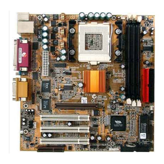
Mainboard User’s Manual Mainboard Components Identify major components on the mainboard via this diagram underneath. Note: Those jumpers of mainboard not appearing in this illustration are for testing only. -
Page 13: I/O Ports
2: Mainboard Installation I/O Ports The illustration below shows a side view of the built-in I/O ports on the mainboard. 1. Use the upper PS/2 port to connect a PS/2 pointing device. 2. Use the lower PS/2 port to connect a PS/2 keyboard. -
Page 14: Installing The Processor
Mainboard User’s Manual Installing the Processor This mainboard has a Socket 423 processor socket. When choosing a processor, consider the performance requirements of the system. Performance is based on the processor design, the clock speed and system bus frequency of the processor, and the quantity of internal cache memory and external cache memory. -
Page 15: Installing Memory Modules
2: Mainboard Installation Installing Memory Modules This mainboard accommodates 168-pin 3.3V unbuffered SDRAM memory modules. The memory chips must be standard or registered SDRAM (Synchronous Dynamic Random Access Memory). The CPU supports 100MHz system bus. The SDRAM DIMMS can synchronously work with 100 MHz or operates over a 133 MHz system bus. - Page 16 Mainboard User’s Manual The mainboard accommodates three memory modules. You must install at least one module in any of the three slots. Each module can be installed with up to 512 MB of memory; total memory capacity is 1.5 GB. Refer to the following to install the memory modules.
-
Page 17: Jumper Settings
2: Mainboard Installation Jumper Settings JP1: Clear CMOS Jumper This jumper enables you to reset BIOS: Turn the system off. 2. Short pins 2 and 3 on JP2. 3. Return the jumper to the normal setting. 4. Turn the system on. The BIOS is returned to the default settings. -
Page 18: The Panel Connectors
Mainboard User’s Manual The Panel Connector The panel connector provide a set of switch and LED connectors found on ATX or Micro ATX cases. Refer to the table below for information. Device Pins Empty Power 6, 8 ON/OFF Reset Switch 5, 7 Green LED 2, 4... -
Page 19: Other Devices Installation
2: Mainboard Installation Other Devices Installation Floppy Diskette Drive Installation The mainboard has a floppy diskette drive (FDD) interface and ships with a diskette drive ribbon cable that supports one or two floppy diskette drives. You can install a 5.25-inch drive and a 3.5- inch drive with various capacities. - Page 20 Mainboard User’s Manual 4 x AGP Slot The 4xAGP slot is used to install a graphics adapter that supports the 4xAGP specification and has a 4xAGP edge connector. CNR Slot The Communications Networking Riser (CNR) slot can be used to insert a CNR card.
-
Page 21: Connecting Optional Devices
2: Mainboard Installation Connecting Optional Devices Refer to the following for information on connecting the mainboard’s optional devices:... - Page 22 Mainboard User’s Manual LAUDIO: Mic/Speaker Out header Signal Name Signal Name Active LINE Out (R) Active LINE Out (L) GND (aLO) GND (aLO) GND (+12) GND (+12) +12V (1A) (Cut away) GND (MIC) Front LINE Out(R) LINE Next (R) Front LINE Out (L) LINE Next (L) GND (tLO) No pin...
- Page 23 2: Mainboard Installation USB2/USB3: Front panel USB headers The mainboard has USB ports installed on the rear edge I/O port array. Some computer cases have a special module that mounts USB ports at the front of the case. If you have this kind of case, use auxiliary USB connectors USB2 and USB3 to connect the front- mounted ports to the mainboard.
- Page 24 Mainboard User’s Manual WOL1/WOM1: Wake On LAN/Wake On Modem If you have installed a LAN card, use the cable provided with the card to plug into the mainboard WOL1 connector. This enables the Wake On LAN (WOL) feature. When your system is in a power- saving mode, any LAN signal automatically resumes the system.
- Page 25 2: Mainboard Installation LSIR: Serial infrared port 2 The mainboard supports a Serial Infrared (SIR) data port. Infrared ports allow the wireless exchange of information between your computer and similarly equipped devices such as printers, laptops, Personal Digital Assistants (PDAs), and other computers. Signal Name No pin IRRX...
-
Page 26: Chapter 3: Bios Setup Utility
3: BIOS Setup Utility Chapter 3 BIOS Setup Utility Introduction The BIOS Setup Utility records computer’s settings and information, such as date and time, type of installed hardware, and various configuration settings. Your computer applies the information to initialize all the components when booting up, and basic functions of overall coordination between system components. -
Page 27: Running The Setup Utility
3: BIOS Setup Utility Running the Setup Utility Each time your computer starts, before the operating system loads, a message appears on the screen that prompts you to “Hit <DEL> if you want to run SETUP”. When you see this message, press the Delete key and the Main menu page of the Setup Utility appears on your monitor. -
Page 28: Standard Cmos Features Page
Mainboard User’s Manual Standard CMOS Features Page This option displays a table of items defining basic information about your system. CMOS Setup Utility – Copyright (C) 1984 – 2001 Award Software Standard CMOS Features Item Help Date (mm:dd:yy) Tue, July 11 2000 Time (hh:mm:ss) 12 : 8 : 59 Menu Level... - Page 29 3: BIOS Setup Utility Video This item defines the video mode of the system. This mainboard has a built-in VGA graphics system; you must leave this item at the default value. Halt On This item defines the operation of the system POST (Power On Self Test) routine.
-
Page 30: Advanced Bios Features Page
Mainboard User’s Manual Advanced BIOS Features Page This page sets up more advanced information about your system. Be more careful to this page. Any changes can affect the operation of your computer. CMOS Setup Utility – Copyright (C) 1984 – 2001 Award Software Advanced BIOS Features Item Help Anti-Virus Protection... - Page 31 3: BIOS Setup Utility CPU L1&L2 All processors that can be installed in this Cache mainboard use internal level 1 (L1) cache and level 2 (L2) cache memory to improve performance. Leave this item at the default value for better performance. CPU L2 Cache This item enables or disables ECC (Error ECC Checking...
- Page 32 Mainboard User’s Manual Typematic Rate Use this item to define how many characters (Chars/Sec) per second are generated when a key is held down. Delay (Msec) Use this item to define how many milliseconds must elapse before a held- down key begins generating repeat characters.
-
Page 33: Advanced Chipset Features Page
3: BIOS Setup Utility Advanced Chipset Features Page This page sets some of the parameters of the mainboard components including the memory, and the system logic. CMOS Setup Utility – Copyright (C) 1984 – 2001 Award Software Advanced Chipset Features DRAM Clock/Drive Control [Press Enter] Item Help... - Page 34 Mainboard User’s Manual AGP & P2P This item has several sub-items: AGP Bridge Control Aperture Size defines the size of the aperture if you use an AGP graphics adapter; AGP Mode allows you to enable or disable the caching of display data for the processor video memory;...
-
Page 35: Integrated Peripherals Page
3: BIOS Setup Utility Integrated Peripherals Page This page sets some of the parameters for peripheral devices connected to the system. CMOS Setup Utility – Copyright (C) 1984 – 2001 Award Software Integrated Peripherals VIA OnChip IDE Device [Press Enter] Item Help VIA On Chip PCI Device [Press Enter]... - Page 36 Mainboard User’s Manual Super I/O Device This item has several sub-items: Hot Key Power ON enables you to select a hot key to turn on the computer; Onboard FDC Controller enables the onboard floppy disk drive controller; Onboard Serial Port 1/2 assigns the I/O address and address and interrupt request (IRQ) for onboard serial port 1 (COM1)/ 2 (COM2);...
- Page 37 3: BIOS Setup Utility USB Keyboard Enable this item if you plan to use a keyboard Support connected through the USB port in a legacy operating system (such as DOS) that does not support Plug and Play. USB Mouse Enable this item if you plan to use a USB Support mouse.
-
Page 38: Power Management Setup Page
Mainboard User’s Manual Power Management Setup Page This page sets some of the parameters for system power management operation. CMOS Setup Utility – Copyright (C) 1984 – 2001 Award Software Power Management Setup ACPI function [Enabled] Item Help ACPI Suspend Type [S1(POS)] Power Management Option [User Define]... - Page 39 3: BIOS Setup Utility ACPI This mainboard supports ACPI (Advanced function Configuration and Power management Interface). Use this item to enable or disable the ACPI feature. ACPI Use this item to define how your system Suspend suspends. In the default, S1(POS), the Type suspend mode is equivalent to a software power down.
- Page 40 Mainboard User’s Manual Video Off This item defines how the video is powered Method down to save power. This item is set to DPMS (Display Power Management Software) by default. MODEM Use If you want an incoming call on a modem to automatically resume the system from a power-saving mode, use this item to specify the interrupt request line (IRQ) that is used by...
- Page 41 3: BIOS Setup Utility saving timeout counters when any activity is detected on the hard disk drive or the floppy diskette drive; When PCI Master is set to Off, any PCI device set as the Master will not power on the system; PowerOn by PCI Card enables PCI activity to wakeup the system from a power saving mode;...
-
Page 42: Pnp/ Pci Configurations Page
Mainboard User’s Manual PnP / PCI Configurations Page This page sets some of the parameters for devices installed on the PCI bus and devices that use the system plug and play capability. CMOS Setup Utility – Copyright (C) 1984 – 2001 Award Software PnP / PCI Configurations PNP OS Installed [No]... - Page 43 3: BIOS Setup Utility IRQ Resources This item allows you to individually assign an interrupt type for interrupts IRQ-3 to IRQ-15. PCI/VGA This item is designed to overcome problems Palette Snoop that can be caused by some non-standard VGA cards. This board includes a built-in VGA system that does not require palette snooping so you must leave this item disabled.
-
Page 44: Pc Health Status
Mainboard User’s Manual PC Health Status On mainboards that support hardware monitoring, this item lets you monitor the parameters for critical voltages, critical temperatures, and fan speeds: CMOS Setup Utility – Copyright (C) 1984 – 2001 Award Software PC Health Status Shutdown Temperature [Disabled] Item Help... -
Page 45: Frequency/Voltage Control
3: BIOS Setup Utility Frequency/Voltage Control This item enables you to set the clock speed and system bus for your system. The clock speed and system bus are determined by the kind of processor you have installed in your system. CMOS Setup Utility –... -
Page 46: Load Fail-Safe Defaults Option
Mainboard User’s Manual Load Fail-Safe Defaults Option This option opens a dialog box that lets you install fail-safe defaults for all appropriate items in the Setup Utility: Press <Y> and then <Enter> to install the defaults. Press <N> and then <Enter> to not install the defaults. The fail-safe defaults place no great demands on the system and are generally stable. -
Page 47: Set Supervisor And User Password Option
3: BIOS Setup Utility Set Supervisor and User Password Option These items can be used to install a password. A Supervisor password takes precedence over a User password, and the Supervisor can limit the activities of a User. To install a password, follow these steps: 1. -
Page 48: Save & Exit Setup Option
Mainboard User’s Manual Save & Exit Setup Option Highlight this item and press <Enter> to save the changes that you have made in the Setup Utility and exit the Setup Utility. When the Save and Exit dialog box appears, press <Y> to save and exit, or press <N>... - Page 49 3: BIOS Setup Utility...
-
Page 50: Chapter 4: Software & Applications
4: Software & Applications Chapter 4 Software & Applications Introduction The support software CD-ROM that is included in the mainboard package contains all the drivers and utility programs needed to properly run our products. Below you can find a brief description of each software program, and the location for your mainboard version. - Page 51 Mainboard User’s Manual Note: The correct path name for each software driver is provided, where D: identifies the CD-ROM drive letter – modify if necessary Bus Master IDE Driver The IDE Bus Master Drivers allows the system to properly manage the IDE channels on the mainboard.
-
Page 52: Auto-Installing Under Windows 98
4: Software & Applications BIOS Update Utility The BIOS Update utility allows you to update the BIOS file on the mainboard to a newer version. You can download the latest version of the BIOS setup available for your mainboard from the website. ... - Page 53 Mainboard User’s Manual The Exit button closes the Auto Setup window. To run the program again, reinsert the CD-ROM disc in the drive or click on AutoRun in the context sensitive menu for the CD-ROM drive icon in a file browser window. Installing Software with Auto Setup To install support software for the system board follow this procedure:...
- Page 54 4: Software & Applications 3.The support software will automatically install. Once any of the installation procedures start, software is automatically installed in sequence. You will need to follow the onscreen instructions, confirm commands and allow the computer to restart as few times as is needed to complete installing whatever software you selected to install.
Need help?
Do you have a question about the M921 Series and is the answer not in the manual?
Questions and answers