Table of Contents
Advertisement
Quick Links
Advertisement
Table of Contents

Subscribe to Our Youtube Channel
Related Manuals for PCchips M957G


Summary of Contents for PCchips M957G
- Page 3 AMI is a trademark of American Megatrends Inc. It has been acknowledged that other brands or product names in this manual are trademarks or the properties of their respective owners. Copyright © 2004 All Rights Reserved M957G Series, V1.0A PM800/November 2004...
-
Page 4: Table Of Contents
Motherboard User’s Guide Table of Contents Trademark ................... i Chapter 1: Introduction ............1 Key Features ..................2 Package Contents ................6 Chapter 2: Motherboard Installation ........7 Motherboard Components ..............8 I/O Ports ..................... 10 Installing the Processor ..............11 Installing Memory Modules ............... - Page 5 Motherboard User’s Guide Static Electricity Precautions Static electricity could damage components on this motherboard. Take the following precautions while unpacking this motherboard and installing it in a system. 1. Don’t take this mainboard and components out of their original static-proof package until you are ready to install them.
- Page 6 USB devices’ connection because it could not recognize these devices. Currently, we are working on such limitations’ solution. As soon as the solution is done, the updated USB drive will be released to our website: www.pcchips.com.tw for your downloading.
-
Page 7: Chapter 1 Introduction
Chapter 1: Introduction Chapter 1 Introduction This motherboard has a LGA775 socket for latest Intel Pentium 4/Celeron processors with Hyper-Threading Tech- nology and Front-Side Bus (FSB) speeds up to 800 MHz. Hyper- Threading Technology, edsigned to take advantage of the multitasking features in Windows XP, gives you the power to do more things at once. -
Page 8: Key Features
Motherboard User’s Guide Key Features The key features of this motherboard include: LGA775 Socket Processor Support Supports the latest Intel Pentium 4/Celeron Series processors Supports up to 800 MHz Front-Side Bus Hyper-Threading technology enables the operating system into thinking it’s hooked up to two processors, allowing two threads to be run in parallel, both on separate ‘logical’... - Page 9 Chapter 1: Introduction PCI to system memory data streaming up to 132Mbyte/sec (data sent to north bridge via high speed Ultra V-Link interface) PCI-2.2 compliant, 32-bit 3.3V PCI interface with 5V tolerant inputs Support three PCI slots of arbitration and decoding for all integrated functions and LPC bus.
- Page 10 Motherboard User’s Guide 16-bit Stereo full-duplex CODEC with independent and variable sampling rate Support for 3.3v digital, 5v analog power supply and low power consumption management Three analog line-level stereo inputs with 5-bit volume control: LINE_IN, CD, AUX Front-Out, Surround-Out, MIC-In and LINE-In Jack Sensing Two analog line-level mono input Standard 48-Pin LQFP...
- Page 11 Chapter 1: Introduction PCI multi-function device consists of two UHCI Host Controller cores for full-/low-speed signaling and one EHCI Host Controller core for high-speed signaling Root hub consists 4 downstream facing ports with inte- grated physical layer transceivers shared by UHCI and EHCI Host Controller, up to eight functional ports Support PCI-Bus Power Management Interface Specifica- tion release 1.1...
-
Page 12: Package Contents
Motherboard User’s Guide Package Contents Your motherboard package ships with the following items: The motherboard The User’s Guide One diskette drive ribbon cable (optional) One IDE drive ribbon cable The Software support CD Optional Accessories You can purchase the following optional accessories for this motherboard. -
Page 13: Chapter 2 Motherboard Installation
Chapter2: Motherboard Installation Chapter 2 Motherboard Installation To install this motherboard in a system, please follow these instructions in this chapter: Identify the motherboard components Install a CPU Install one or more system memory modules Make sure all jumpers and switches are set correctly Install this motherboard in a system chassis (case) Connect any extension brackets or cables to headers/ connectors on the motherboard... -
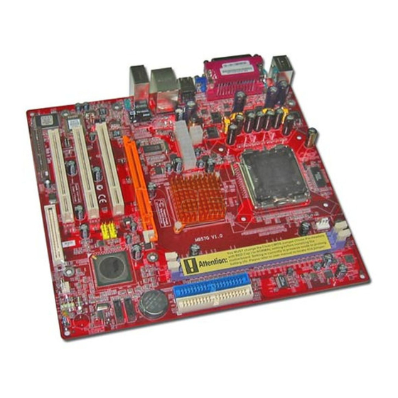
Page 14: Motherboard Components
Motherboard User’s Guide Motherboard Components LGA775 Socket CPU_FAN DDR1 DDR2 IDE1 IDE2 ATX1 AUDIO1 AGP1 USB2/3 SATA1-2 FDD1 SYSFAN1 SPK1 CNR1 PCI1-3... - Page 15 Chapter2: Motherboard Installation LABEL COMPONENTS CPU_FAN CPU Fan connector DDR1-2 Two 184-pin DDR SDRAM sockets ATX1 Standard 20-Pin ATX Power connector Standard 4-Pin ATX Power connector IDE1/2 IDE connector SYSFAN1 Chasis cooling fan connector SATA1-2 Serial ATA connectors Clear CMOS jumper Front Panel Switch/LED header FDD1 Floppy Disk Drive connector...
-
Page 16: I/O Ports
Motherboard User’s Guide I/O Ports The illustration below shows a side view of the built-in I/O ports on the motherboard. PS/2 Mouse Use the upper PS/2 port to connect a PS/2 pointing device. Use the lower PS/2 port to connect a PS/2 PS/2 Keyboard keyb oard. -
Page 17: Installing The Processor
Chapter2: Motherboard Installation Installing the Processor This motherboard has a LGA775 socket for the latest Intel Pentium 4/Celeron processors. When choosing a processor, consider the performance requirements of the system. Perfor- mance is based on the processor design, the clock speed and system bus frequency of the processor, and the quantity of internal cache memory and external cache memory. - Page 18 Motherboard User’s Guide Be careful not to touch the contacts. C. Install the CPU on the socket • Orientate CPU package to the socket. Make sure you match triangle marker to pin 1 location. D. Close the load plate • Slightly push down the load plate onto the tongue side, and hook the lever.
-
Page 19: Installing Memory Modules
Chapter2: Motherboard Installation Installing Memory Modules This motherboard accommodates two 184-pin 2.5V DIMM sockets (Dual Inline Memory Module) for unbuffered DDR 400/ 333/266/200 memory modules (Double Data Rate SDRAM) and maximum 2.0 GB installed memory. DDR SDRAM is a type of SDRAM that supports data transfers on both edges of each clock cycle (the rising and falling edges), effectively doubling the memory chip’s data throughput. - Page 20 Motherboard User’s Guide Memory Module Installation Procedure These modules can be installed with up to 2 GB system memory. Refer to the following to install the memory module. Push down the latches on both sides of the DIMM socket. Align the memory module with the socket. There is a notch on the DIMM socket that you can install the DIMM module in the correct direction.
-
Page 21: Jumper Settings
Chapter2: Motherboard Installation Jumper Settings Connecting two pins with a jumper cap is SHORT; removing a jumper cap from these pins, OPEN. JP3: Clear CMOS Jumper Use this jumper to clear the contents of the CMOS memory. You may need to clear the CMOS memory if the settings in the Setup Utility are incorrect and prevent your motherboard from operating. -
Page 22: Install The Motherboard
Motherboard User’s Guide Install the Motherboard Install the motherboard in a system chassis (case). The board is a Micro ATX size motherboard. You can install this motherboard in an ATX case. Make sure your case has an I/O cover plate matching the ports on this motherboard. -
Page 23: Connecting Optional Devices
Chapter2: Motherboard Installation Please refer to the following list of the SW1 pin assignments. Signal Signal 1 HD_LED_P(+) 2 FP PWR/SLP(+) 3 HD_LED_N(-) 4 FP PWR/SLP(-) 5 RESET_SW_N(-) 6 POWER_SW_P(+) 7 RESET_SW_P(+) 8 POWER_SW_N(-) RSVD_DNU 10 KEY Connecting Optional Devices Refer to the following for information on connecting the motherboard’s optional devices: AUDIO1... - Page 24 Motherboard User’s Guide AUDIO1: Front Panel Audio Header This header allows the user to install auxiliary front-oriented microphone and line-out ports for easier access. Signal Signal AUD_MIC AUD_GND AUD_MIC_BIAS AUD_VCC AUD_FPOUT_R AUD_RET_R HP_ON AUD_FPOUT_L 10 AUD_RET_L USB2/USB3: Front Panel USB Header The motherboard has USB ports installed on the rear edge I/O port array.
- Page 25 Chapter2: Motherboard Installation SPK1: Speaker Header Connect the cable from the PC speaker to the SPK1 header on the motherboard. Signal Signal 1 Vcc5 3 GND 4 SPKR IR1: Infrared Header The infrared port allows the wireless exchange of information between your computer and similarly equipped devices such as printers, laptops, Personal Digital Assistants (PDAs), and other computers.
-
Page 26: Install Other Devices
Motherboard User’s Guide Install Other Devices Install and connect any other devices in the system following the steps below. IDE1 IDE2 SATA2 SATA1 FDD1... - Page 27 Chapter2: Motherboard Installation Floppy Disk Drive The motherboard ships with a floppy disk drive cable that can support one or two drives. Drives can be 3.5" or 5.25" wide, with capacities of 360K, 720K, 1.2MB, 1.44MB, or 2.88MB. Install your drives and connect power from the system power supply.
- Page 28 Motherboard User’s Guide forms. It provides you a faster transfer rate of 150 MB/s. If you have installed a Serial ATA hard drive, you can connect the Serial ATA cables to the Serial ATA hard drive or the connecter on the motherboard.
-
Page 29: Expansion Slots
Chapter2: Motherboard Installation Expansion Slots This motherboard has one AGP, one CNR and three 32-bit PCI slots. AGP1 PCI1 PCI2 PCI3 CNR1... - Page 30 Motherboard User’s Guide Follow the steps below to install an AGP/CNR/PCI/PCI Express expansion card. Locate the AGP, CNR, PCI and PCI Express slots on the motherboard. Remove the blanking plate of the slot from the system chassis. Install the edge connector of the expansion card into the slot.
-
Page 31: Chapter 3 Bios Setup Utility
Chapter 3: BIOS Setup Utility Chapter 3 BIOS Setup Utility Introduction The BIOS Setup Utility records settings and information of your computer, such as date and time, the type of hardware installed, and various configuration settings. Your computer applies the information to initialize all the components when booting up and basic functions of coordination between system components. -
Page 32: Running The Setup Utility
Motherboard User’s Guide Running the Setup Utility Every time you start your computer, a message appears on the screen before the operating system loading that prompts you to “Hit <DEL>if you want to run SETUP”. Whenever you see this message, press the Delete key, and the Main menu page of the Setup Utility appears on your monitor. -
Page 33: Standard Cmos Setup Page
Chapter 3: BIOS Setup Utility Standard CMOS Setup Page This page displays a table of items defining basic information about your system. CMOS SETUP UTILITY – Copyright (C) 1985-2004, American Megatrends, Inc. Standard CMOS Setup System Time 00:01:25 Help Item System Date Thu 05/06/2004 User [Enter], [TAB] or... -
Page 34: Advanced Setup Page
Motherboard User’s Guide Advanced Setup Page This page sets up more advanced information about your system. Handle this page with caution. Any changes can affect the operation of your computer. CMOS SETUP UTILITY – Copyright (C) 1985-2004, American Megatrends, Inc. Advanced Setup Help Item Quick Boot... - Page 35 Chapter 3: BIOS Setup Utility Boot To OS/2> 64MB Enable this item if you are booting the OS/2 operating system and you have more than 64MB of system memory installed. AGP Aperture Size This item defines an AGP for the graphics. Leave this item at the default value 64MB.
-
Page 36: Features Setup Page
Motherboard User’s Guide Features Setup Page This page sets up some parameters for peripheral devices connected to the system. CMOS SETUP UTILITY – Copyright (C) 1985-2004, American Megatrends, Inc. Features Setup Help Item OnBoard Floppy Controller Enabled Serial Port1 Address 3F8/IRQ4 Allows BIOS to OnBoard IR Port... - Page 37 Chapter 3: BIOS Setup Utility Port), EPP (Enhanced Parallel Port) or EPP&ECP (Enhanced Parallel Port & Extended Capabilities Port). ECP Mode DMA Channel Use this item to assign the DMA Channel under ECP Mode function. Parallel Port IRQ Use this item to assign IRQ to the parallel port. OnBoard PCI IDE Controller Use this item to enable or disable either or both of the onboard Primary and Secondary IDE channels.
-
Page 38: Power Management Setup Page
Motherboard User’s Guide Power Management Setup Page This page sets some parameters for system power management operation. CMOS SETUP UTILITY – Copyright (C) 1985-2004, American Megatrends, Inc. Power Management Setup ACPI Aware O/S Help Item Power Management Enabled Enable / Disable Suspend Time Out Disabled ACPI support for... - Page 39 Chapter 3: BIOS Setup Utility Resume on RTC Alarm The system can be turned off with a software command. If you enable this item, the system can automatically resume at a fixed time based on the system’s RTC (realtime clock). Use the items below this one to set the date and time of the wake-up alarm.
-
Page 40: Pci/Plug And Play Setup Page
Motherboard User’s Guide PCI / Plug and Play Setup Page This page sets up some parameters for devices installed on the PCI bus and those utilizing the system plug and play capability. CMOS SETUP UTILITY – Copyright (C) 1985-2004, American Megatrends, Inc. PCI / Plug and Play Setup Primary Graphics Adapter Help Item... -
Page 41: Bios Security Features Setup Page
Chapter 3: BIOS Setup Utility BIOS Security Features Setup Page This page helps you install or change a password. CMOS SETUP UTILITY – Copyright (C) 1985-2004, American Megatrends, Inc. BIOS Security Features Setup Security Settings Help Item Install or Change Supervisor Password : Not Installed the password. -
Page 42: Cpu Pnp Setup Page
Motherboard User’s Guide CPU PnP Setup Page This page helps you manually configure the mainboard for the CPU. The system will automatically detect the type of installed CPU and make the appropriate adjustments to the items on this page. CMOS SETUP UTILITY – Copyright (C) 1985-2004, American Megatrends, Inc. CPU PnP Setup Manufacturer Intel... -
Page 43: Hardware Monitor Page
Chapter 3: BIOS Setup Utility Hardware Monitor Page This page sets up some parameters for the hardware monitoring function of this motherboard. CMOS SETUP UTILITY – Copyright (C) 1985-2004, American Megatrends, Inc. Hardware Monitor Setup -=- System Hardware Monitor-=- Help Item Vcore : 1.280 V Vdimm... -
Page 44: Save Changes And Exit
Motherboard User’s Guide Save Changes and Exit Highlight this item and press <Enter> to save the changes that you have made in the Setup Utility configuration. When the Save Changes and Exit dialog box appears, select [OK] to save and exit, or [Cancel] to return to the main menu. -
Page 45: Chapter 4 Software & Applications
Chapter 4: Software & Applications Chapter 4 Software & Applications Introduction This chapter describes the contents of the support CD-ROM that comes with the motherboard package. The support CD-ROM contains all useful software, necessary drivers and utility programs to properly run our products. More program information is available in a README file, located in the same directory as the software. -
Page 46: Installing Support Software
Motherboard User’s Guide Installing Support Software Insert the support CD-ROM disc in the CD-ROM drive. When you insert the CD-ROM disc in the system CD- ROM drive, the CD automatically displays an Auto Setup screen. The screen displays three buttons of Setup, Browse CD and Exit on the right side, and three others Setup, Application and ReadMe at the bottom. - Page 47 Chapter 4: Software & Applications Auto-Installing under Windows 2000/XP If you are under Windows 2000/XP, please click the Setup button to run the software auto-installing program while the Auto Setup screen pops out after inserting the support CD-ROM: The installation program loads and displays the following screen.
-
Page 48: Bundled Software Installation
Motherboard User’s Guide Installing under Windows NT or Manual Installation If you are under Windows NT, the auto-installing program doesn’t work out; or you have to do the manual installation, please follow this procedure while the Auto Setup screen pops out after insert- ing the support CD-ROM: Click the ReadMe to bring up a screen, and then click the Install Path at the bottom of the screen. -
Page 49: Hyper-Threading Cpu
Chapter 4: Software & Applications Hyper-Threading CPU While you are in Windows Task Manager, please push down ctrl+Alt Del keys. A dual CPU appears in the CPU Usage History&Device Manager under WinXP. Note: Hyper-Threading Function only works under WINXP Operating System; therefore, disable it under other Operating System.
Need help?
Do you have a question about the M957G and is the answer not in the manual?
Questions and answers