Table of Contents
Advertisement
Quick Links
Advertisement
Table of Contents

Related Manuals for PCchips M925G Series


Summary of Contents for PCchips M925G Series
- Page 3 Microsoft Corporation. AMI is a trademark of American Megatrends Inc. It has been acknowledged that all mentioned brands or product names are trademarks or registered trademarks of their respective holders. Copyright © 2004 All Rights Reserved M925G Series, V9.1B P4M266A/March 2004...
-
Page 4: Table Of Contents
Table of Contents Trademark ..................I Static Electricity Precautions..........III Pre-Installation Inspection.............III Chapter 1: Introduction..............1 Key Features................2 Package Contents ..............6 Chapter 2: Motherboard Installation ..........7 Motherboard Components ............8 I/O Ports ..................8 Installing the Processor............9 Installing Memory Modules ..........10 Jumper Settings ..............12 The Panel Connector .............13 Other Devices Installation .............14 Expansion Slots Installation ..........14... -
Page 5: Static Electricity Precautions
Static Electricity Precautions Static electricity could damage components on this motherboard. Take the following precautions while unpacking this motherboard and installing it in a system. 1. Don’t take this motherboard and components out of their original static-proof package until you are ready to install them. - Page 6 USB devices’ connection because it could not recognize these devices. Currently, we are working on such limitations’ solution. As soon as the solution is done, the updated USB drive will be released to our website: www.pcchips.com for your downloading.
-
Page 7: Chapter 1: Introduction
Chapter 1 Introduction This motherboard has a Socket 478 for the Intel Pentium 4 / Prescott type of processors supporting front side bus (FSB) speeds up to 533/400 MHz. This motherboard has the VIA P4M266A Northbridge and VT8235 Southbridge chipsets that support AC’ 97 audio codec, and provide Ultra DMA 133/100/66/33 function. -
Page 8: Key Features
Key Features This motherboard has these key features: Socket 478 Processor ♦ The PGA Socket 478 ♦ Supports Intel Pentium 4 / Prescott series CPU ♦ Supports a front-side bus (FSB) of 533/400 MHz Chipset There are VIA P4M266A Northbridge and VT8235 Southbridge in this chipset in accordance with an innovative and scalable architecture with proven reliability and performance. - Page 9 Built-in Graphics System ♦ P4M266A integrates S3® ProSavage 8 graphics accelerator into a single chip. P4M266A brings mainstream graphics performance to the Value PC with leading-edge 2D, 3D and DVD video acceleration into a cost effective package. Based on its capabilities, P4M266A is an ideal solution for the consumer, corporate mobile users and entry level professionals.
- Page 10 Expansion Options The motherboard comes with the following expansion options: ♦ Three 32-bit PCI slots ♦ One 4xAGP slot ♦ One CNR (Communications and Networking Riser) slot Onboard I/O Ports The motherboard has a full set of I/O ports and connectors: ♦...
- Page 11 USB 2.0 ♦ Compliant with Universal Serial Bus Specification Revision 2.0 ♦ Compliant with Intel’s Enhanced Host Controller Interface Specification Revision 0.95 ♦ Compliant with Universal Host Controller Interface Specification Revision 1.1 ♦ PCI multi-function device consists of two UHCI Host Controller cores for full-/low-speed signaling and one EHCI Host Controller core for high-speed signaling ♦...
-
Page 12: Package Contents
Package Contents Your motherboard package contains the following items: The motherboard The User’s Manual One diskette drive ribbon cable (optional) One IDE drive ribbon cable The Software support CD Optional Accessories You can purchase the following optional accessories for this motherboard. -
Page 13: Chapter 2: Motherboard Installation
Chapter 2 Motherboard Installation To install this motherboard in a system, please follow these instructions in this chapter: Identify the motherboard components Install a CPU Install one or more system memory modules Make sure all jumpers and switches are set correctly Install this motherboard in a system chassis (case) Connect any extension brackets or cables to connectors on the motherboard... -
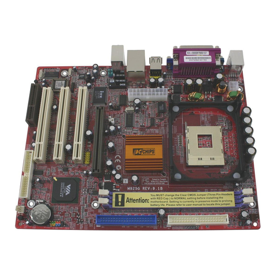
Page 14: Motherboard Components
Motherboard Components Identify major components on the motherboard via this diagram underneath. I/O Ports The illustration below shows a side view of the built-in I/O ports on the motherboard. (shared (optional) with JUSBC) -
Page 15: Installing The Processor
PS/2 Mouse Use the upper PS/2 port to connect a PS/2 pointing device. PS/2 Keyboard Use the lower PS/2 port to connect a PS/2 keyboard. LPT1 Use LPT1 to connect printers or other parallel communications devices. COM1 Use the COM port to connect serial devices such as mice or fax/modems. -
Page 16: Installing Memory Modules
CPU Installation Procedure Follow these instructions to install the CPU: Pin1 Socket-478 CPU_FAN 1. Unhook the locking lever of the CPU socket. Pull the locking lever away from the socket and raising it to the upright position. 2. Match the pin1 corner marked as the beveled edge on the CPU with the pin1 corner on the socket. - Page 17 DDR SDRAM provides 1.6 GB/s or 2.1 GB/s data transfer rate depending on whether the bus is 100 MHz or 133 MHz. DDR SDRAM uses additional power and ground lines and requires 184-pin 2.5V unbuffered DIMM module. DDR1 DDR2 Installation Procedure These modules can be installed with up to 2 GB system memory.
-
Page 18: Jumper Settings
Jumper Settings AUDIO1 JP1A1 JP1B1 JBAT1 PANEL1 JBAT1: Clear CMOS Jumper This jumper is to clear the contents of CMOS memory. You may need to clear the CMOS memory if the settings in the Setup Utility are incorrect that prevents your motherboard from operating. To clear the CMOS memory, disconnect all the power cables from the motherboard and then move the jumper cap into the CLEAR setting for a few seconds. -
Page 19: The Panel Connector
The Panel Connector Audio 1 If there are a headphone jack or/and a microphone jack on the front panel, connect the cables to the PANEL1 on the motherboard. Device Pins Line Out(L) Line Out(L) Line Out (L) 9, 10 (Pin 9) (Pin 10) Empty Empty... -
Page 20: Other Devices Installation
Other Devices Installation Floppy Diskette Drive Installation The motherboard has a floppy diskette drive (FDD) interface and ships with a diskette drive ribbon cable that supports one or two floppy diskette drives. You can install a 5.25-inch drive and a 3.5- inch drive with various capacities. -
Page 21: Connecting Optional Devices
PCI (Peripheral Components Interconnect) Slot You can install the 32-bit PCI interface expansion cards in the slots. CNR1 AGP1 1. Remove a blanking plate from the system case corresponding to the slot you are going to use. 2. Install the edge connector of the expansion card into the expansion slot. - Page 22 SIR1 SPK1: Speaker Connector Connect the cable from the PC speaker to the SPK1 header on the motherboard. Signal Signal SPKR USB2: Front panel USB header The motherboard has USB ports installed on the rear edge I/O port array. Some computer cases have a special module that mounts USB ports at the front of the case.
- Page 23 Please check the pin assignment of the cable and the USB header on the motherboard. Make sure the pin assignment will match before plugging in. Any incorrect usage may cause unexpected damage to the system. The vendor won’t be responsible for any incidental or consequential damage arising from the usage or misusage of the purchased product.
-
Page 24: Chapter 3: Bios Setup Utility
Chapter 3 BIOS Setup Utility Introduction The BIOS Setup Utility records settings and information of your computer, such as date and time, the type of hardware installed, and various configuration settings. Your computer applies those information to initialize all the components when booting up and basic functions of coordination between system components. -
Page 25: Running The Setup Utility
Running the Setup Utility Every time you start your computer, a message appears on the screen before the operating system loading that prompts you to “Hit <DEL>if you want to run SETUP”. Whenever you see this message, press the Delete key, and the Main menu page of the Setup Utility appears on your monitor. -
Page 26: Standard Cmos Setup Page
Standard CMOS Setup Page This page helps you set up basic information such as the date and time, the IDE devices, and the diskette drives. AMIBIOS SETUP – STANDARD CMOS SETUP (C) 2000 American Megatrends, Inc. All Rights Reserved Date (mm/dd/yy) : Mon Apr 28, 2003 Time (hh/mm/ss) : 17:09:30 32Bit Type... -
Page 27: Advanced Setup Page
Advanced Setup Page This page sets up more advanced information about your system. Be more careful to this page. Any changes can affect the operation of your computer. AMIBIOS SETUP – ADVANCED SETUP (C) 2000 American Megatrends, Inc. All Rights Reserved Quick Boot Enabled AGP Aperture Size... - Page 28 S.M.A.R.T. for Enable this item if any IDE hard disks Hard Disks support the S.M.A.R.T. (Self- Monitoring, Analysis and Reporting Technology) feature. BootUp Num- This item determines if the Num Lock Lock key is active or inactive at system start- up time.
- Page 29 DRAM CAS# This item determines the operation of Latency DRAM memory CAS (column address strobe). It is recommended that you leave this item at the default value. The 2T setting requires faster memory that specifically supports this mode. DRAM Bank Enable this item to increase DRAM Interleave memory speed.
-
Page 30: Power Management Setup Page
Hyper-Threading If your P4 CPU is not HT CPU, this item Function will be hidden. If your P4 CPU is HT CPU, BIOS will show this item. You can set "Disabled" or "Enabled" to control HT CPU support in O.S. Set “Enabled” to test HT CPU function. - Page 31 Suspend Time This sets the timeout for Suspend mode in minutes. If the time selected passes without any system activity, the computer will enter power-saving Suspend mode. Resume On The system can be turned off with a RTC Alarm / software command.
-
Page 32: Pci/Plug And Play Setup Page
PCI / Plug and Play Setup Page This page sets up some parameters for devices installed on the PCI bus and those utilizing the system plug and play capability. AMIBIOS SETUP – PCI / PLUG AND PLAY SETUP (C) 2000 American Megatrends, Inc. All Rights Reserved Share Memory Size 32MB Primary Graphics Adapter... -
Page 33: Load Optimal Settings
Load Optimal Settings If you select this item and press Enter a dialog box appears. If you press Y, and then Enter, the Setup Utility loads a set of fail-safe default values. These default values are not very demanding and they should allow your system to function with most kinds of hardware and memory chips. - Page 34 OnBoard FDC Use this item to enable or disable the onboard floppy disk drive interface. OnBoard Serial Use this item to enable or disable the PortA onboard COM1 serial port, and to assign a port address. OnBoard IR Use this item to enable or disable the Port onboard infrared port, and to assign a port address.
-
Page 35: Cpu Pnp Setup Page
CPU PnP Setup Page This page helps you manually configure the motherboard for the CPU. The system will automatically detect the type of installed CPU and make the appropriate adjustments to the items on this page. AMIBIOS SETUP – CPU PnP SETUP ©2000 American Megatrends, Inc. -
Page 36: Change Password
CPU / System These items display CPU and system Temperature temperature measurement. FANs & These items indicate cooling fan speeds in Voltage RPM and the various system voltage Measurements measurements. Change Password If you highlight this item and press Enter, a dialog box appears that you can enter a Supervisor password. -
Page 37: Chapter 4: Software & Applications
Chapter 4 Software & Applications Introduction This chapter describes the contents of the support CD-ROM that comes with the motherboard package. The support CD-ROM contains all useful software, necessary drivers and utility programs to properly run our products. More program information is available in a README file, located in the same directory as the software. -
Page 38: Installing Support Software
Installing Support Software 1.Insert the support CD-ROM disc in the CD-ROM drive. 2.When you insert the CD-ROM disc in the system CD-ROM drive, the CD automatically displays an Auto Setup screen. 3.The screen displays three buttons of Setup, Browse CD and Exit on the right side, and three others Setup, Application and ReadMe at the bottom. - Page 39 Auto-Installing under Windows 98/ME/2000/XP If you are under Windows 98/ME/2000/XP, please click the Setup button to run the software auto-installing program while the Auto Setup screen pops out after inserting the support CD-ROM: 1. The installation program loads and displays the following screen.
-
Page 40: Bundled Software Installation
Installing under Windows NT or Manual Installation If you are under Windows NT, the auto-installing program doesn’t work out; or you have to do the manual installation, please follow this procedure while the Auto Setup screen pops out after inserting the support CD-ROM: 1. -
Page 41: Hyper-Threading Cpu
Hyper-Threading CPU You must update BIOS to initiate BIOS Hyper Threading Function and use HT CPU function under WinXP Operating System; if not, please disable this option. ♦ When BIOS detects the HT CPU, it shows the “Hyper Threading Function (default Disabled)” option, which you must set Enabled if you want to test HT CPU function.
Need help?
Do you have a question about the M925G Series and is the answer not in the manual?
Questions and answers