Table of Contents
Advertisement
Quick Links
This publication, including all photographs, illustrations and
software, is protected under international copyright laws, with all
rights reserved. Neither this manual, nor any of the material
contained herein, may be reproduced without the express written
consent of the manufacturer.
The information in this document is subject to change without
notice. The manufacturer makes no representations or warranties
with respect to the contents hereof and specifically disclaims any
implied warranties of merchantability or fitness for any particular
purpose. Further, the manufacturer reserves the right to revise this
publication and to make changes from time to time in the content
hereof without obligation of the manufacturer to notify any person
of such revision or changes.
Trademarks
IBM, VGA, and PS/2 are registered trademarks of International
Business Machines.
Intel, Pentium/II/III, Pentium 4, Celeron and MMX are registered
trademarks of Intel Corporation.
Microsoft, MS-DOS and Windows 98/ME/NT/2000/XP are
registered trademarks of Microsoft Corporation.
PC-cillin is a registered trademark of Trend Micro Inc.
AMI is a registered trademark of American Megatrends Inc.
SiS is a trademark of Silicon Integrated System Corporation.
Other names used in this publication may be trademarks and are
acknowledged.
Copyright © 2003
All Rights Reserved
M935D Series, V2.0A
S650GX/September 2003
Advertisement
Table of Contents

Related Manuals for PCchips M935D Series


Summary of Contents for PCchips M935D Series
- Page 1 AMI is a registered trademark of American Megatrends Inc. SiS is a trademark of Silicon Integrated System Corporation. Other names used in this publication may be trademarks and are acknowledged. Copyright © 2003 All Rights Reserved M935D Series, V2.0A S650GX/September 2003...
-
Page 2: Table Of Contents
Table of Contents Trademark ..................I Static Electricity Precautions..........III Pre-Installation Inspection .............III Features & Checklist Translations..........V Chapter 1: Introduction..............1 Key Features ................2 Package Contents..............5 Chapter 2: Mainboard Installation..........6 Mainboard Components ............7 I/O Ports...................8 Installing the Processor............9 Installing Memory Modules ..........10 Jumper Settings..............11 Install the Mainboard.............12 Connecting Optional Devices ..........13... -
Page 3: Static Electricity Precautions
Static Electricity Precautions Components on this mainboard can be damaged by static electricity. Take the following precautions when unpacking the mainboard and installing it in a system. 1. Keep the mainboard and other components in their original static-proof packaging until you are ready to install them. 2. - Page 4 USB devices’ connection because it could not recognize these devices. Currently, we are working on such limitations’ solution. As soon as the solution is done, the updated USB drive will be released to our website: www.pcchips.com.tw for your downloading.
-
Page 5: Features & Checklist Translations
Features & Checklist Translations Liste de contrôle Le coffret de votre carte mère contient les éléments suivants : La carte mère Le Manuel utilisateur Un câble plat pour lecteur de disquette (optionnel) Une câble plat pour lecteur IDE CD de support de logiciels Caractéristiques Prise en charge du Processeur Socket-478 Processeur... - Page 6 • Quatre ports USB2.0 de panneau arrière et deux ports USB2.0 supplémentaires (Prise USB interne JUSB1) • Prises audio pour microphone, ligne d’entrée et ligne de sortie • Supporte le fonctionnement en 10/100Mbps et le fonctionnement LAN Ethernet en half/full duplex intégré...
- Page 7 Checkliste Die Verpackung Ihres Mainboards enthält folgende Teile: Mainboard Handbuch Bandkabel für Floppylaufwerke (optional) Bandkabel für IDE-Laufwerke Software-CD Ausstattung Unterstütz Socket-478-Prozessoren Prozessor • PGA Socket 478 • Unterstützung für Intel Pentium 4-CPUs • Unterstützung von bis zu 533 MHz Front-Side Bus Chipsatz Dieser Chipsatz besteht aus einer SiS650GX Northbridge und einer SiS962L Southbridge.
- Page 8 • Audioanschlüsse für Mikrofon, line-in und line-out • Unterstützt Betrieb mit 10/100 MB/Sek. sowie Halb- IIntegriertes /Vollduplexbetrieb Ethernet LAN • Kompatibel mit IEEE 802.3/802.3u (optional) • Unterstützt IEEE 802.3u Clause 28 Auto Negotiation • Unterstützt Betrieb im Link Down-Energiesparmodus • Unterstützt Base Line Winder (BLW)- Kompensation •...
- Page 9 Lista L’imballo della scheda madre é composto da: La scheda madre Il manuale Una piattina per il collegamento dei drive (opzionale) Una piattina IDE Il CD con il Software di supporto Caratteristiche Dotata di Socket 478 per Processori Processor • Il Socket 478 PGA •...
- Page 10 • Supporto delle impostazioni per la negoziazione automatica IEEE 802.3u • Supporto delle operazioni nella modalità Link Down Power Saving • Supporto della compensazione Base Line Winder (BLW) • Equalizzazione adattabile • Compliant with Universal Serial Bus Specification Revision 2.0 USB 2.0 •...
- Page 11 LiSTA DE VERIFICACIÓN El paquete de su placa principal contiene los sigtes. ítems: La placa principal El Manual del Usuario Un cable cinta para el lector de disquete (optativo) Un cable cinta para el lector IDE CD de Software de soporte Características Soporte de Procesador Socket-478 Procesador...
- Page 12 • Soporta la operación de 10/100Mbps y de medio/full duplex Ethernet LAN • Conformidad IEEE 802.3/802.3u Incorporado • Soporta la autonegociación de clásura 28 de IEEE 802.3u (optativo) • Soporta operación bajo el modo Link Down Power Saving (Ahorro de Suministro de Vínculo) •...
- Page 13 Lista de verificação A embalagem da sua placa principal contém os seguintes itens: A placa principal O Manual do Utilizador Um cabo para a unidade de disquetes (opcional) Um cabo para a unidade IDE CD de suporte para o software Características Suporte do Processador Socket-478 Processador...
- Page 14 • Jacks audio para microfone, line-in e line-out • Suporta o funcionamento 10/100Mbps em half/full duplex Ethernet LAN • Compatível com IEEE 802.3/802.3u Integrada • Suporta IEEE 802.3u, classe 28 com negociação automática (opcional) • Suporta o funcionamento no modo Poupança de Energia com Ligação Inactiva •...
- Page 15 检查单 您的主板包装含有以下项目: 主板 用户手册 一根磁盘驱动器扁平电缆(可选) 一根 IDE 驱动器扁平电缆 软件支持 CD 功能 支持 Socket-478 处理器 处理器 • PGA Socket 478 • 支持 Intel Pentium 4 系列 CPU • 支持 533/400 MHz 前端总线 芯片组 芯片组包含 SiS650GX 北桥和 SiS962L 南桥, 它基于一种新型的、 可 扩展的架构,能提供已经证明的可靠性和高性能。以下是芯片组 和它 们的功能:...
- Page 16 • 支持 10/100Mbps 工作和半/全双工工作 内建以太网 • 符合 IEEE 802.3/802.3u 标准 • 支持 IEEE 802.3u 第 28 项的自协商 (可选) • 支持链路故障节电模式下操作 • 支持基线漂移 (BLW) 补偿 • 自适应均衡 • 符合通用串行总线规格 2.0 版本 USB 2.0 • 符合 Intel 0.95 版本的增强主控器接口规格 • 符合 1.1 版本的通用主控器接口规格 •...
-
Page 17: Chapter 1: Introduction
Chapter 1 Introduction This mainboard has a Socket-478 processor socket for Intel Pentium 4 processors with front-side bus (FSB) speeds up to 533 MHz. This mainboard integrates the SiS650GX Northbridge along with SiS962L Southbridge chipsets that supports built-in AC97 Codec , 2 DDR modules up to 2GB system memory, and provides Ultra DMA 33/66/100/133 function. -
Page 18: Key Features
Key Features The key features of this mainboard include: Socket-478 Processor ♦ The PGA Socket 478 ♦ Supports Intel Pentium 4 series CPU ♦ Supports up to 533 MHz Front-Side Bus Chipset There are SiS650GX Northbridge and SiS962L Southbridge in this chipset in accordance with an innovative and scalable architecture with proven reliability and performance. - Page 19 ♦ Supports RTC Alarm, Wake On Modem, AC97 Wake-Up and USB Wake-Up Onboard VGA ♦ Supports AGP V2.0 Compliant ♦ Supports AGP 4X/2X interface and Fast Write Transaction ♦ Supports high performance & high quality 3D Accelerator—A built-in 256-bit 3D engine, up to 143 MHz 3D engine clock speed ♦...
- Page 20 ♦ Four back-panel USB2.0 ports and extra two USB2.0 ports (onboard USB connector JUSB1) ♦ Audio jacks for microphone, line-in and line-out Hardware Monitoring ♦ Built-in hardware monitoring for CPU & System temperatures, fan speeds and mainboard voltages. Onboard Flash ROM ♦...
-
Page 21: Package Contents
Package Contents Your mainboard package contains the following items: The mainboard The User’s Manual One diskette drive ribbon cable (optional) One IDE drive ribbon cable Software support CD Optional Accessories You can purchase the following optional accessories for this mainboard. Extended USB module CNR v.90 56K Fax/Modem card Card Reader... -
Page 22: Chapter 2: Mainboard Installation
Chapter 2 Mainboard Installation To install this mainboard in a system, please follow the instructions in this chapter: Identify the mainboard components Install a CPU Install one or more system memory modules Verify that all jumpers or switches are set correctly Install the mainboard in a system chassis (case) Connect any extension brackets or cables to connectors on the mainboard... -
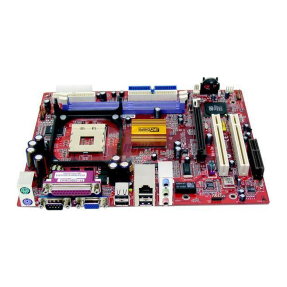
Page 23: Mainboard Components
Mainboard Components Use the diagram below to identify the major components on the mainboard. Note: Any jumpers on your mainboard not appearing in the illustration above are for testing only. -
Page 24: I/O Ports
I/O Ports The illustration below shows a side view of the built-in I/O ports on the mainboard. (optional) (shared with READ1) PS/2 Mouse Use the upper PS/2 port to connect a PS/2 pointing device. PS/2 Keyboard Use the lower PS/2 port to connect a PS/2 keyboard. -
Page 25: Installing The Processor
Installing the Processor This mainboard has a Socket 478 processor socket. When choosing a processor, consider the performance requirements of the system. Performance is based on the processor design, the clock speed and system bus frequency of the processor, and the quantity of internal cache memory and external cache memory. -
Page 26: Installing Memory Modules
Installing Memory Modules This mainboard accommodates two 184-pin 2.5V unbuffered Double Data Rate SDRAM (DDR SDRAM) Dual Inline Memory Module (DIMM) sockets, and supports up to 2.0 GB of 333 MHz DDR SDRAM. DDR SDRAM is a type of SDRAM that supports data transfers on both edges of each clock cycle (the rising and falling edges), effectively doubling the memory chip’s data throughput. -
Page 27: Jumper Settings
DIMM module in the correct direction. Match the cutout on the DIMM module with the notch on the DIMM socket. 3. Install the DIMM module into the socket and press it firmly down until it is seated correctly. The socket latches are levered upwards and latch on to the edges of the DIMM. -
Page 28: Install The Mainboard
Install the Mainboard Install the mainboard in a system chassis (case). The board is a Micro ATX size mainboard. You can install this mainboard in an ATX case. Ensure your case has an I/O cover plate that matches the ports on this mainboard. Install the mainboard in a case. -
Page 29: Connecting Optional Devices
Connecting Optional Devices Refer to the following for information on connecting the mainboard’s optional devices: AUDIO2 READ1 JUSB1 SPK1 SPK1: Speaker Connector Connect the cable from the PC speaker to the SPK1 connector on the mainboard. Signal Signal SPKR AUDIO2: Front Panel Audio Connector This connector allows the user to install auxiliary front-oriented microphone and line-out ports for easier access. - Page 30 JUSB1: Front panel USB Connector The mainboard has USB ports installed on the rear edge I/O port array. Additionally, some computer cases have USB ports at the front of the case. If you have this kind of case, use auxiliary USB connector JUSB1 to connect the front-mounted ports to the mainboard.
- Page 31 Please check the pin assignment of the cable and the USB header on the mainboard. Make sure the pin assignment will match before plugging in. Any incorrect usage may cause unexpected damage to the system. The vendor won’t be responsible for any incidental or consequential damage arising from the usage or misusage of the purchased product.
-
Page 32: Install Other Devices
Install Other Devices Install and connect other devices in the system as steps below. IDE2 FLOPPY IDE1 Floppy Disk Drive The mainboard ships with a floppy disk drive cable that can support one or two drives. Drives can be 3.5” or 5.25” wide, with capacities of 360K, 720K, 1.2MB, 1.44MB, or 2.88MB. - Page 33 Install the device(s) and connect power from the system power supply. Use the cable provided to connect the device(s) to the Primary IDE channel connector IDE1 on the mainboard. If you want to install more IDE devices, you can purchase a second IDE cable and connect one or two devices to the Secondary IDE channel connector IDE2 on the mainboard.
-
Page 34: Expansion Slots
Expansion Slots This mainboard has one AGP, one CNR and two 32-bit PCI slots. AGP1 CNR1 PCI2 PCI1 Follow the steps below to install one AGP/CNR/PCI expansion card. 1. Locate the AGP, CNR or PCI slots on the mainboard. 2. Remove the blanking plate of the slot from the system chassis. 3. -
Page 35: Chapter 3: Bios Setup Utility
Chapter 3 BIOS Setup Utility Introduction The BIOS Setup Utility records settings and information about your computer such as the date and time, the kind of hardware installed, and various configuration settings. Your computer uses this information to initialize all the components when booting up and functions as the basis for coordination between system components. -
Page 36: Running The Setup Utility
Running the Setup Utility Each time your computer starts, before the operating system loads, a message appears on the screen that prompts you to “Hit <DEL> if you want to run SETUP”. When you see this message, press the Delete key and the Main menu page of the Setup Utility appears on your monitor. -
Page 37: Standard Cmos Setup Page
Standard CMOS Setup Page Use this page to set basic information such as the date, the time, the IDE devices, and the diskette drives. If you press the F3 key, the system will automatically detect and configure the hard disks on the IDE channels. -
Page 38: Advanced Setup Page
Floppy Drive A Use these items to set the size and capacity of Floppy Drive B the floppy diskette drive(s) installed in the system. Advanced Setup Page This page sets up more advanced information in the system. Be more carful with this page. Making changes can affect the operation of your computer. - Page 39 Try Other Boot If you enable this item, the system will Device also search for other boot devices if it fails to find an operating system from the first two locations. S.M.A.R.T. for Hard Enable this item if any IDE hard disks Disks support the S.M.A.R.T.
- Page 40 System BIOS If you enable this item, a segment of the Cacheable system BIOS will be copied to main memory for faster execution. Share Memory Size This item lets you allocate a portion of the main memory for the onboard VGA display application with five options of 4/8/16/32/64 MB.
-
Page 41: Power Management Setup Page
Auto Detect When this item is enabled, BIOS will DIMM/PCI Clk disable the clock signal of free DIMM/PCI slots. Spread Spectrum If you enable spread spectrum, it can significantly reduce the EMI(Electro- Magnetic Interference) generated by the system. DOS Flat Mode This item enables BIOS entering the DOS protected mode without other software supporting under the DOS... - Page 42 Power Use this item to select a power management Management scheme. Both APM and ACPI are supported. Suspend Time Out This sets the timeout for Suspend mode in minutes. If the time selected passes without any system activity, the computer will enter power-saving Suspend mode.
-
Page 43: Pci/Plug And Play Setup Page
PCI / Plug and Play Setup Page This page sets some of the parameters for devices installed on the PCI bus and devices that use the system plug and play capability. AMIBIOS SETUP – PCI / PLUG AND PLAY SETUP (C) 2000 American Megatrends, Inc. -
Page 44: Load Optimal Settings
Load Optimal Settings If you select this item and press Enter a dialog box appears. If you press Y, and then Enter, the Setup Utility loads a set of fail-safe default values. These default values are not very demanding and they should allow your system to function with most kinds of hardware and memory chips. - Page 45 OnBoard FDC Use this item to enable or disable the onboard floppy disk drive interface. OnBoard Serial Use these items to enable or disable the Port onboard COM1 serial port, and to assign a port address. OnBoard IR Port Use this item to enable or disable the onboard infrared port, and to assign a port address.
-
Page 46: Cpu Pnp Setup Page
USB Function for Enable this item if you plan to use the USB ports on this mainboard in a DOS environment. ThumbDrive for Enable this item to make a small portion of memory storage device for the USB ports. CPU PnP Setup Page This page lets you manually configure the mainboard for the CPU. -
Page 47: Hardware Monitor Page
Hardware Monitor Page This page sets some of the parameters for the hardware monitoring function of this mainboard. AMIBIOS SETUP – HARDWARE MONITOR (C) 2000 American Megatrends, Inc. All Rights Reserved *** System Hardware *** Vcore 1.712V Vcc 1.8V 2.496V Vcc 3.3V 3.392V 4.945V... -
Page 48: Exit
at start-up, depending on the setting of the Password Check item in Advanced Setup. Change or Remove the Password Highlight this item, press Enter and type in the current password. At the next dialog box, type in the new password, or just press Enter to disable password protection. -
Page 49: Chapter 4: Software & Applications
Chapter 4 Software & Applications Introduction This chapter describes the contents of the support CD-ROM that comes with the mainboard package. The support CD-ROM contains all useful software, necessary drivers and utility programs to properly run our products. More program information is available in a README file, located in the same directory as the software. -
Page 50: Installing Support Software
Installing Support Software 1.Insert the support CD-ROM disc in the CD-ROM drive. 2.When you insert the CD-ROM disc in the system CD-ROM drive, the CD automatically displays an Auto Setup screen. 3.The screen displays three buttons of Setup, Browse CD and Exit on the right side, and three others Setup, Application and ReadMe at the bottom. - Page 51 Auto-Installing under Windows 98/ME/2000/XP If you are under Windows 98/ME/2000/XP, please click the Setup button to run the software auto-installing program while the Auto Setup screen pops out after inserting the support CD-ROM: 1. The installation program loads and displays the following screen.
-
Page 52: Bundled Software Installation
Installing under Windows NT or Manual Installation If you are under Windows NT, the auto-installing program doesn’t work out; or you have to do the manual installation, please follow this procedure while the Auto Setup screen pops out after inserting the support CD-ROM: 1.
Need help?
Do you have a question about the M935D Series and is the answer not in the manual?
Questions and answers