Table of Contents
Advertisement
Quick Links
Mainboard User's Manual
This publication, photographs, illustrations and software are under
the protection of international copyright laws and all rights
reserved. It does not allow any reproduction of this manual,
content and any materials contained herein without the written
consent of the authentic manufacturer.
The information in this manual is subject to change without notice.
The manufacturer does neither represent nor warrant the contents
hereof; and specifically disclaims any implied warranties of
merchantability or fitness for any particular purpose. Furthermore,
the manufacturer reserves the right to revise and change this
publication from time to time, without the obligation of notifying
any person of such revision or changes.
Trademarks
IBM, VGA, and PS/2 are registered trademarks of International
Business Machines.
Intel, Pentium/II/III, Pentium 4, Celeron and MMX are registered
trademarks of Intel Corporation.
Microsoft, MS-DOS and Windows 98/ME/NT/2000/XP are
registered trademarks of Microsoft Corporation.
PC-cillin is a trademark of Trend Micro Inc.
AMI is a trademark of American Megatrends Inc.
MediaRing Talk is a registered trademark of MediaRing Inc.
3Deep is a registered trademark of E-Color Inc.
It has been acknowledged that all mentioned brands or product
names are trademarks or registered trademarks of their respective
holders.
Copyright © 2002
All Rights Reserved
M902 Series, V3.0
I845D/August 2002
Advertisement
Table of Contents

Subscribe to Our Youtube Channel
Related Manuals for PCchips M902 Series


Summary of Contents for PCchips M902 Series
- Page 1 MediaRing Talk is a registered trademark of MediaRing Inc. 3Deep is a registered trademark of E-Color Inc. It has been acknowledged that all mentioned brands or product names are trademarks or registered trademarks of their respective holders. Copyright © 2002 All Rights Reserved M902 Series, V3.0 I845D/August 2002...
- Page 2 USB devices’ connection because it could not recognize these devices. Currently, we are working on such limitations’ solution. As soon as the solution is done, the updated USB drive will be released to our website: www.pcchips.com.tw for your downloading.
-
Page 3: Table Of Contents
Mainboard User’s Manual Table of Contents Chapter 1: Introduction..............1 Key Features................2 Package Contents..............5 Static Electricity Precautions..........6 Pre-Installation Inspection............6 Chapter 2: Mainboard Installation..........7 Mainboard Components............8 I/O Ports..................9 Installing the Processor............10 Installing Memory Modules..........11 Jumper Settings..............13 Install The Mainboard............15 Optional Extension Brackets..........16 Install Other Devices............18 Expansion Slots ..............21 Chapter 3: BIOS Setup Utility............23... - Page 4 Mainboard User’s Manual...
-
Page 5: Chapter 1: Introduction
1: Introduction Chapter 1 Introduction This mainboard has a Socket-478 support for Intel Pentium4 processors with front-side bus (FSB) speeds up to 533 MHz This mainboard has the Intel 845D chipset that contains Intel 82845 Memory Controller Hub and Intel 82801BA I/O Controller Hub. -
Page 6: Key Features
Mainboard User’s Manual Key Features This mainboard has these key features: Socket-478 Processor Supports Intel Pentium 4 series CPUs Supports up to 533 MHz Front-Side Bus Memory Support Two 168-pin DIMM slots for SDRAM memory modules Two 184-pin DIMM slots for DDR SDRAM memory modules ... - Page 7 1: Introduction Onboard I/O Ports The mainboard has a full set of I/O ports and connectors: Two PS/2 ports for mouse and keyboard Two serial ports One parallel port One MIDI/game port Six USB ports (two back-panel USB 2.0 ports, onboard USB headers providing maximum four extra ports: header JUSB2 for USB 2.0 and header USB2 for USB 1.1) ...
- Page 8 Mainboard User’s Manual BIOS Firmware This mainboard uses AMI BIOS that enables users to configure many system features including the following: Power management Wake-up alarms CPU parameters and memory timing CPU and memory timing The firmware can also be used to set parameters for different processor clock speeds.
-
Page 9: Package Contents
1: Introduction Package Contents Attention: This mainboard serial has three models, M902L (LAN), M902 and M902LUL (LAN, USB 2.0). Please contact your local supplier for more information about your purchased model. Each model will support different specification listed as below: Model Specification M902L... -
Page 10: Static Electricity Precautions
Mainboard User’s Manual Static Electricity Precautions Static electricity could damage components on this mainboard. Take the following precautions while unpacking this mainboard and installing it in a system. 1. Don’t take this mainboard and components out of their original static-proof package until you are ready to install them. 2. -
Page 11: Chapter 2: Mainboard Installation
2: Mainboard Installation Chapter 2 Mainboard Installation To install this mainboard in a system, please follow these instructions in this chapter: Identify the mainboard components Install a CPU Install one or more system memory modules Make sure all jumpers and switches are set correctly ... -
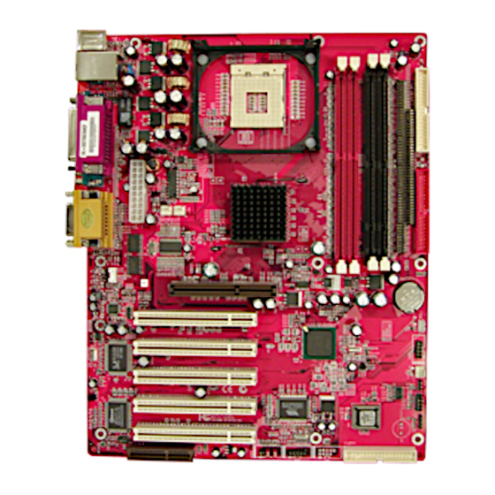
Page 12: Mainboard Components
Mainboard User’s Manual Mainboard Components Identify major components on the mainboard via this diagram underneath. Note: Any jumpers on your mainboard that do not appear in this illustration are for testing only. -
Page 13: I/O Ports
2: Mainboard Installation I/O Ports The illustration below shows a side view of the built-in I/O ports on the mainboard. Parallel port (LPT1) Game port PS/2 port mouse PS/2 Serial port Serial port Microphone keyboard ports COM 1 COM 2 Line-in Line-out 1. -
Page 14: Installing The Processor
Mainboard User’s Manual Installing the Processor This mainboard has a Socket 478 processor socket. When choosing a processor, consider the performance requirements of the system. Performance is based on the processor design, the clock speed and system bus frequency of the processor, and the quantity of internal cache memory and external cache memory. -
Page 15: Installing Memory Modules
2: Mainboard Installation Installing Memory Modules This mainboard accommodates 168-pin 3.3V/184-pin 2.5V unbuffered SDRAM memory modules. The memory chips must be standard or registered SDRAM (Synchronous Dynamic Random Access Memory). The CPU supports 100MHz system bus. The SDRAM DIMMs and DDRs can synchronously work with 100 MHz or operates over a 133 MHz memory bus. - Page 16 Mainboard User’s Manual Installation Procedure The mainboard accommodates two memory modules. You must install at least one module in any of the three slots. Each module can be installed with up to 2 GB system memory. Refer to the following to install the memory modules. 1.
-
Page 17: Jumper Settings
2: Mainboard Installation Jumper Settings JT10 JP1: DDR/SDR DRAM Type Selector This jumper enables to select DDR or SDR DRAM type. Function Jumper Setting SDRAM Short Pins 1-2 Short Pins 2-3 JT1~JT10: DDR/SDR DRAM Type Selector This jumper enables to select DDR or SDR DRAM type. Function Jumper Setting SDRAM... - Page 18 Mainboard User’s Manual JP2: Clear CMOS Jumper Use this jumper to clear the contents of the CMOS memory. You may need to clear the CMOS memory if the settings in the Setup Utility are incorrect and prevent your mainboard from operating. To clear the CMOS memory, disconnect all the power cables from the mainboard and then move the jumper cap into the CLEAR setting for a few seconds.
-
Page 19: Install The Mainboard
2: Mainboard Installation Install the Mainboard Install the mainboard in a system chassis (case). The board is an ATX size mainboard with a twin-tier of I/O ports. You can install this mainboard in an ATX case. Ensure that your case has an I/O cover plate that matches the ports on this mainboard. -
Page 20: Optional Extension Brackets
Mainboard User’s Manual Connect the case switches and indicator LEDs to the PANEL1 header. Here is a list of the PANEL1 header’s pin assignments. Signal Signal HDD_LED_P ACPI-LED HDD_LED_N ACPI-LED RESET_SW_N POWER-BT RESET_SW_P POWER-BT If there are a headphone jack or/and a microphone jack on the front header on the panel, connect the cables to the AUDIO1 mainboard. - Page 21 2: Mainboard Installation Extended USB Module This module bracket has four USB ports for more USB devices (USB port JUSB2, USB2). JUSB2 USB2 Signal Signal VERG_FP_USBPWR0 VERG_FP_USBPWR0 USB_FP_P0- USB_FP_P1- USB_FP_P0+ USB_FP_P1+ GROUND GROUND USB_FP_OC0 1. Locate the JUSB2/USB2 header on the mainboard. 2.
-
Page 22: Install Other Devices
Mainboard User’s Manual Install Other Devices Install and connect any other devices in the system following the steps below. FLOPPY IDE1 IDE2 Floppy Disk Drive The mainboard ships with a floppy disk drive cable that can support one or two drives. Drives can be 3.5” or 5.25” wide, with capacities of 360K, 720K, 1.2MB, 1.44MB, or 2.88MB. - Page 23 2: Mainboard Installation If you want to install more IDE devices, you can purchase a second IDE cable and connect one or two devices to the Secondary IDE channel connector IDE2 on the mainboard. If you have two devices on the cable, one must be Master and one must be Slave. Internal Sound Connections If you have installed a CD-ROM drive or DVD-ROM drive, you can connect the drive audio cable to the onboard sound system.
- Page 24 Mainboard User’s Manual WOL1: Wake On LAN If you have installed a LAN card, use the cable provided with the card to plug into the mainboard WOL1 connector. This enables the Wake On LAN (WOL1) feature. When your system is in a power-saving mode, any LAN signal automatically resumes the system.
-
Page 25: Expansion Slots
2: Mainboard Installation Expansion Slots This mainboard has one AGP, one CNR and five 32-bit PCI slots. CNR1 PCI1 PCI2 PCI3 PCI4 PCI5 Follow the steps below to install an AGP/CNR/PCI expansion card. 1. Locate the AGP, CNR or PCI slots on the mainboard. 2. - Page 26 Mainboard User’s Manual CNR Slot This slot is used to insert CNR(Communications and Networking Riser) cards including LAN, Modem, and Audio functions.
-
Page 27: Chapter 3: Bios Setup Utility
3: BIOS Setup Utility Chapter 3 BIOS Setup Utility Introduction The BIOS Setup Utility records settings and information of your computer, such as date and time, the type of hardware installed, and various configuration settings. Your computer applies those information to initialize all the components when booting up and basic functions of coordination between system components. -
Page 28: Running The Setup Utility
Mainboard User’s Manual Running the Setup Utility Every time you start your computer, a message appears on the screen before the operating system loading that prompts you to “Hit <DEL>if you want to run SETUP”. Whenever you see this message, press the Delete key, and the Main menu page of the Setup Utility appears on your monitor. -
Page 29: Standard Cmos Setup Page
3: BIOS Setup Utility Standard CMOS Setup Page This page displays a table of items defining basic information about your system. AMIBIOS SETUP – STANDARD CMOS SETUP (C) 2000 American Megatrends, Inc. All Rights Reserved Date (mm/dd/yy) : Tue Aug 20, 2002 Time (hh/mm/ss) : 11:12:13 32Bit Type... - Page 30 Mainboard User’s Manual...
-
Page 31: Advanced Setup Page
3: BIOS Setup Utility Advanced Setup Page This page sets up more advanced information about your system. Handle this page with caution. Any changes can affect the operation of your computer. AMIBIOS SETUP – ADVANCED SETUP (C) 2000 American Megatrends, Inc. All Rights Reserved Quick Boot Enabled Boot Device... - Page 32 Mainboard User’s Manual Quick Boot If you enable this item, the system starts up more quickly be elimination some of the power on test routines. Boot Device Use these items to determine the device Boot Device order the computer uses to look for an Boot Device operating system to load at start-up time.
- Page 33 3: BIOS Setup Utility SDRAM CAS# This item determines the operation of Latency SDRAM memory CAS (column address strobe). It is recommended that you leave this item at the default value. The 2T setting requires faster memory that specifically supports this mode. SDRAM RAS# Select the number of CPU clocks Precharge...
-
Page 34: Power Management Setup Page
Mainboard User’s Manual Power Management Setup Page This page sets some parameters for system power management operation. AMIBIOS SETUP – POWER MANAGEMENT SETUP (C) 2000 American Megatrends, Inc. All Rights Reserved Keyboard Power On Function Disabled Specific Key for PowerOn ACPI Aware O/S Power Management/APM Enabled... - Page 35 3: BIOS Setup Utility Suspend Time This sets the timeout for Suspend mode in Out (Minute) minutes. If the time selected passes without any system activity, the computer will enter power-saving Suspend mode. LAN/Ring The system can be turned off with a PowerOn software command.
-
Page 36: Pci/Plug And Play Setup Page
Mainboard User’s Manual PCI / Plug and Play Setup Page This page sets up some parameters for devices installed on the PCI bus and those utilizing the system plug and play capability. AMIBIOS SETUP – PCI / PLUG AND PLAY SETUP (C) 2000 American Megatrends, Inc. -
Page 37: Load Optimal Settings
3: BIOS Setup Utility Load Optimal Settings If you select this item and press Enter a dialog box appears. If you press Y, and then Enter, the Setup Utility loads a set of fail-safe default values. These default values are not very demanding and they should allow your system to function with most kinds of hardware and memory chips. -
Page 38: Features Setup Page
Mainboard User’s Manual Features Setup Page This page sets up some parameters for peripheral devices connected to the system. AMIBIOS SETUP – FEATURES SETUP (C) 2000 American Megatrends, Inc. All Rights Reserved USB Function Support Enabled RTL8100B & VT6202 Support Enabled USB Function For DOS Disabled... - Page 39 3: BIOS Setup Utility USB Function Enable this item if you plan to use the USB Support ports on this mainboard. Enable this item if you plan to use the USB USB Function ports on this mainboard in a DOS For DOS environment.
- Page 40 Mainboard User’s Manual Select parallel port. OnBoard This item enables or disables the I/O Game Port address for the game port. RTL8100B & This item enables or disables the chipset VT6202 RTL8100B&VT6202 for LAN&USB 2.0. Support...
-
Page 41: Cpu Pnp Setup Page
3: BIOS Setup Utility CPU PnP Setup Page This page helps you manually configure the CPU of this mainboard. The system will automatically detect the type of installed CPU and make the appropriate adjustments to these items on this page. AMIBIOS SETUP –... -
Page 42: Hardware Monitor Page
Mainboard User’s Manual Hardware Monitor Page This page sets up some parameters for the hardware monitoring function of this mainboard. AMIBIOS SETUP – HARDWARE MONITOR (C) 2000 American Megatrends, Inc. All Rights Reserved *** System Hardware *** CPU Temperature 59C/138F SYSTEM Temperature 28C/82F CPU Fan Speed... -
Page 43: Change Password
3: BIOS Setup Utility Change Password If you highlight this item and press Enter, a dialog box appears that you can enter a Supervisor password. You can enter no more than six letters or numbers. Press Enter after you have typed in the password. - Page 44 Mainboard User’s Manual...
-
Page 45: Chapter 4: Software & Applications
4: Software & Applications Chapter 4 Software & Applications Introduction This chapter describes the contents of the support CD-ROM that comes with the mainboard package. The support CD-ROM contains all useful software, necessary drivers and utility programs to properly run our products. More program information is available in a README file, located in the same directory as the software. -
Page 46: Installing Support Software
Mainboard User’s Manual Installing Support Software 1.Insert the support CD-ROM disc in the CD-ROM drive. 2.When you insert the CD-ROM disc in the system CD-ROM drive, the CD automatically displays an Auto Setup screen. 3.The screen displays three buttons of Setup, Browse CD and Exit on the right side, and three others Setup, Application and ReadMe at the bottom. - Page 47 4: Software & Applications Auto-Installing under Windows 98/ME/2000/XP If you are under Windows 98/ME/2000/XP, please click the Setup button to run the software auto-installing program while the Auto Setup screen pops out after inserting the support CD-ROM: 1. The installation program loads and displays the following screen.
-
Page 48: Bundled Software Installation
Mainboard User’s Manual Installing under Windows NT or Manual Installation If you are under Windows NT, the auto-installing program doesn’t work out; or you have to do the manual installation, please follow this procedure while the Auto Setup screen pops out after inserting the support CD-ROM: 1.
Need help?
Do you have a question about the M902 Series and is the answer not in the manual?
Questions and answers