Table of Contents
Advertisement
Quick Links
Mainboard User's Manual
This publication, photographs, illustrations and software are under
the protection of international copyright laws and all rights
reserved. It does not allow any reproduction of this manual,
content and any materials contained herein without the written
consent of the authentic manufacturer.
The information in this manual is subject to change without notice.
The manufacturer does neither represent nor warrant the contents
hereof; and specifically disclaims any implied warranties of
merchantability or fitness for any particular purpose. Furthermore,
the manufacturer reserves the right to revise and change this
publication from time to time, without the obligation of notifying
any person of such revision or changes.
Trademarks
IBM, VGA, and PS/2 are registered trademarks of International
Business Machines.
Intel, Pentium/II/III, Pentium 4, Celeron and MMX are registered
trademarks of Intel Corporation.
Microsoft, MS-DOS and Windows 98/ME/NT/2000/XP are
registered trademarks of Microsoft Corporation.
PC-cillin is a trademark of Trend Micro Inc.
AMI is a trademark of American Megatrends Inc.
MediaRing Talk is a registered trademark of MediaRing Inc.
3Deep is a registered trademark of E-Color Inc.
It has been acknowledged that all mentioned brands or product
names are trademarks or registered trademarks of their respective
holders.
Copyright © 2002
All Rights Reserved
M922 Series, V5.0A
VT8753/September 2002
Advertisement
Table of Contents

Related Manuals for PCchips M922 Series


Summary of Contents for PCchips M922 Series
- Page 1 MediaRing Talk is a registered trademark of MediaRing Inc. 3Deep is a registered trademark of E-Color Inc. It has been acknowledged that all mentioned brands or product names are trademarks or registered trademarks of their respective holders. Copyright © 2002 All Rights Reserved M922 Series, V5.0A VT8753/September 2002...
- Page 2 USB devices’ connection because it could not recognize these devices. Currently, we are working on such limitations’ solution. As soon as the solution is done, the updated USB drive will be released to our website: www.pcchips.com.tw for your downloading.
-
Page 3: Table Of Contents
Mainboard User’s Manual Table of Contents Chapter 1: Introduction..............1 Key Features................2 Package Contents..............6 Static Electricity Precautions..........7 Pre-Installation Inspection............7 Chapter 2: Mainboard Installation..........9 Mainboard Components............10 I/O Ports................11 Installing the Processor............12 Installing Memory Modules..........13 Jumper Settings..............15 The Panel Connectors............17 Other Devices Installation.............19 Expansion Slots Installation..........20 Connecting Optional Devices ..........21 Chapter 3: BIOS Setup Utility............25... - Page 4 Mainboard User’s Manual...
-
Page 5: Chapter 1: Introduction
1: Introduction Chapter 1 Introduction This mainboard has a Socket-478 processor socket for Intel Pentium 4 type of processors supporting front side bus (FSB) speeds up to 533 MHz This mainboard has the VIA P4X333 Northbridge and VT8235/8233ACE Southbridge chipsets that support AC 97 audio codec, and provide Ultra DMA 33/66/100/133 function. -
Page 6: Key Features
Mainboard User’s Manual Key Features This mainboard has these key features: Socket-478 Processor The PGA Socket 478 Supports Intel Pentium 4 series CPUs Supports up to 533 MHz Front-Side Bus Chipset There are P4X333 Northbridge and VT8235 / 8233ACE Southbridge in this chipset in accordance with an innovative and scalable architecture with proven reliability and performance. - Page 7 1: Introduction Memory Support The mainboard accommodates 2 DDR + 2 SDR 168 pin, 3.3V DIMM sockets with a total capacity of 1 GB system memory. Supports DDR up to 333MHz memory bus This mainboard includes a 4xAGP slot that provides four times the bandwidth of the original AGP specification.
- Page 8 Mainboard User’s Manual Six USB ports (two back-panel ports, onboard USB headers providing maximum four extra ports: headers USB1 & USB2) Audio jacks for microphone, line-in and line-out Fast Ethernet LAN (for VT8235 SB only) Built-in 10BaseT/100BaseTX Ethernet LAN ...
- Page 9 1: Introduction CPU and memory timing The firmware can also be used to set parameters for different processor clock speeds. Bundled Software PC-Cillin 2000 provides automatic virus protection under Windows 98/ME/NT/2000/XP MediaRing Talk provides PC to PC or PC to Phone internet phone communication ...
-
Page 10: Package Contents
Mainboard User’s Manual Package Contents Attention: This mainboard serial has three models, M922LU(LAN,USB 2.0), M922U(USB 2.0, without LAN) and M922. Please contact your local supplier for more information about your purchased model. Each model will support different specification listed as below: Model Specification M922LU... -
Page 11: Static Electricity Precautions
1: Introduction Static Electricity Precautions Static electricity could damage components on this mainboard. Take the following precautions while unpacking this mainboard and installing it in a system. 1. Don’t take this mainboard and components out of their original static-proof package until you are ready to install them. 2. - Page 12 Mainboard User’s Manual...
-
Page 13: Chapter 2: Mainboard Installation
2: Mainboard Installation Chapter 2 Mainboard Installation To install this mainboard in a system, please follow these instructions in this chapter: Identify the mainboard components Install a CPU Install one or more system memory modules Make sure all jumpers and switches are set correctly ... -
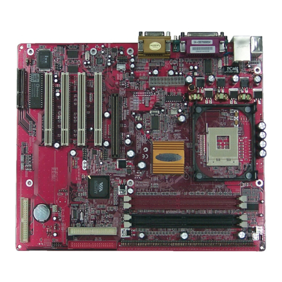
Page 14: Mainboard Components
Mainboard User’s Manual Mainboard Components Identify major components on the mainboard via this diagram underneath. Note: Any jumpers on your mainboard that do not appear in this illustration are for testing only. -
Page 15: I/O Ports
2: Mainboard Installation I/O Ports The illustration below shows a side view of the built-in I/O ports on the mainboard. Parallel port (LPT1) Game port PS/2 port mouse PS/2 Serial port Serial port Microphone keyboard ports COM 1 COM 2 Line-in Line-out 1. -
Page 16: Installing The Processor
Mainboard User’s Manual Installing the Processor This mainboard has a Socket 478 processor socket. When choosing a processor, consider the performance requirements of the system. Performance is based on the processor design, the clock speed and system bus frequency of the processor, and the quantity of internal cache memory and external cache memory. -
Page 17: Installing Memory Modules
2: Mainboard Installation Installing Memory Modules This mainboard accommodates 168-pin 3.3V/184-pin 2.5V unbuffered SDRAM memory modules. The memory chips must be standard or registered SDRAM (Synchronous Dynamic Random Access Memory). The CPU supports 100/133MHz system bus. The SDRAM DIMMs and DDRs can synchronously work with 100 MHz or operates over a 133 MHz system bus. - Page 18 Mainboard User’s Manual Installation Procedure The mainboard accommodates two memory modules. You must install at least one module in any of the three slots. Each module can be installed with up to 1GB system memory. Refer to the following to install the memory modules. 1.
-
Page 19: Jumper Settings
2: Mainboard Installation Jumper Settings JP1A1 JP1B1 J2A/B/C/D JBAT1 J3A/B/C/D JBAT1: Clear CMOS Jumper Use this jumper to clear the contents of the CMOS memory. You may need to clear the CMOS memory if the settings in the Setup Utility are incorrect and prevent your mainboard from operating. To clear the CMOS memory, disconnect all the power cables from the mainboard and then move the jumper cap into the CLEAR setting for a few seconds. - Page 20 Mainboard User’s Manual JP1: DRAM Voltage (VCC) This jumper enables to select voltage of DRAM. Function Jumper Setting 2.5V (DDR) Open Pins 1-2 3V (SDR) Short Pins 1-2 J2A/B/C/D, J3A/B/C/D: DDR/SDR DRAM Type Selector This jumper enables to select the type of DDR or SDR DRAM.
-
Page 21: The Panel Connectors
2: Mainboard Installation The Panel Connector PANEL1 If there are a headphone jack or/and a microphone jack on the front panel, connect the cables to the PANEL1 on the mainboard. Device Pins Line Out (L) 9, 10 Empty Line Out (R) 5, 6 +5V Audio VCCMIC... - Page 22 Mainboard User’s Manual J16: LAN LED Indicator This connector is attached to LAN device that needs a LED indicator. Device Pins Link LED 1, +2 LINK ACT LED +3, 4 Note: The plus sign (+) indicates a pin which must be connected to a positive voltage.
-
Page 23: Other Devices Installation
2: Mainboard Installation Other Devices Installation Floppy Diskette Drive Installation The mainboard has a floppy diskette drive (FDC) interface and ships with a diskette drive ribbon cable that supports one or two floppy diskette drives. You can install a 5.25-inch drive and a 3.5- inch drive with various capacities. -
Page 24: Expansion Slots Installation
Mainboard User’s Manual Expansion Slots Installation This mainboard has four 32-bit PCI (Peripheral Components Interconnect) expansion slots, one 4xAGP slot, and one CNR slot. PCI Slots PCI slots are used to install expansion cards that have the 32-bit PCI interface. 4x AGP Slot The 4xAGP slot is used to install a graphics adapter that supports the 4xAGP specification and has a 4xAGP edge connector. -
Page 25: Connecting Optional Devices
2: Mainboard Installation Connecting Optional Devices Refer to the following for information on connecting the mainboard’s optional devices: USB1 SIR1 USB2 SPK1 Note: If the VT8233ACE Southbridge is installed, the mainboard doesn’t support the header USB2. - Page 26 Mainboard User’s Manual J12: Sleep Switch This header is connected to the sleep button for suspending the computer’s activity if pushing the button. Or, the computer is automatically suspended after passing a period of time. Signal -EXTSMI SPK1: Speaker Connector Connect the cable from the PC speaker to the SPK1 header on the mainboard.
- Page 27 2: Mainboard Installation If you have installed a modem, use the cable provided with the modem to plug into the mainboard WOM1 connector. This enables the Wake On Modem (WOM1) feature. When your system is in a power-saving mode, any modem signal automatically resumes the system.
- Page 28 Mainboard User’s Manual SIR1: Serial infrared port The mainboard supports a Serial Infrared (SIR1) data port. Infrared ports allow the wireless exchange of information between your computer and similarly equipped devices such as printers, laptops, Personal Digital Assistants (PDAs), and other computers. Signal Signal IRTX...
-
Page 29: Chapter 3: Bios Setup Utility
3: BIOS Setup Utility Chapter 3 BIOS Setup Utility Introduction The BIOS Setup Utility records settings and information of your computer, such as date and time, the type of hardware installed, and various configuration settings. Your computer applies those information to initialize all the components when booting up and basic functions of coordination between system components. -
Page 30: Running The Setup Utility
Mainboard User’s Manual Running the Setup Utility Every time you start your computer, a message appears on the screen before the operating system loading that prompts you to “Hit <DEL>if you want to run SETUP”. Whenever you see this message, press the Delete key, and the Main menu page of the Setup Utility appears on your monitor. -
Page 31: Standard Cmos Setup Page
3: BIOS Setup Utility Standard CMOS Setup Page This page displays a table of items defining basic information about your system. AMIBIOS SETUP – STANDARD CMOS SETUP (C) 2000 American Megatrends, Inc. All Rights Reserved Date (mm/dd/yy) : Mon Sept 05, 2002 Time (hh/mm/ss) : 17:08:22 32Bit Type... - Page 32 Mainboard User’s Manual...
-
Page 33: Advanced Setup Page
3: BIOS Setup Utility Advanced Setup Page This page sets up more advanced information about your system. Handle this page with caution. Any changes can affect the operation of your computer. AMIBIOS SETUP – ADVANCED SETUP (C) 2000 American Megatrends, Inc. All Rights Reserved Quick Boot Enabled AGP Aperture Size... - Page 34 Mainboard User’s Manual S.M.A.R.T. for Enable this item if any IDE hard disks Hard Disks support the S.M.A.R.T. (Self- Monitoring, Analysis and Reporting Technology) feature. BootUp Num- This item determines if the Num Lock Lock key is active or inactive at system start- up time.
- Page 35 3: BIOS Setup Utility SDRAM CAS# This item determines the operation of Latency SDRAM memory CAS (column address strobe). It is recommended that you leave this item at the default value. The 2T setting requires faster memory that specifically supports this mode. SDRAM Bank Enable this item to increase SDRAM Interleave...
-
Page 36: Power Management Setup Page
Mainboard User’s Manual Power Management Setup Page This page sets some parameters for system power management operation. AMIBIOS SETUP – POWER MANAGEMENT SETUP (C) 2000 American Megatrends, Inc. All Rights Reserved ACPI Aware O/S Power Management Enabled Suspend Time Out Disabled Hard Disk Time Out Standby... - Page 37 3: BIOS Setup Utility Resume On The system can be turned off with a RTC Alarm / software command. If you enable this item, Date / Hour / the system can automatically resume at a Minute / fixed time based on the system’s RTC Second (realtime clock).
-
Page 38: Pci/Plug And Play Setup Page
Mainboard User’s Manual PCI / Plug and Play Setup Page This page sets up some parameters for devices installed on the PCI bus and those utilizing the system plug and play capability. AMIBIOS SETUP – PCI / PLUG AND PLAY SETUP (C) 2000 American Megatrends, Inc. -
Page 39: Load Optimal Settings
3: BIOS Setup Utility Load Optimal Settings If you select this item and press Enter a dialog box appears. If you press Y, and then Enter, the Setup Utility loads a set of fail-safe default values. These default values are not very demanding and they should allow your system to function with most kinds of hardware and memory chips. -
Page 40: Features Setup Page
Mainboard User’s Manual Features Setup Page This page sets up some parameters for peripheral devices connected to the system. AMIBIOS SETUP – FEATURES SETUP (C) 2000 American Megatrends, Inc. All Rights Reserved OnBoard FDC Enabled OnBoard Serial PortA 3F8h/COM1 OnBoard Serial PortB 2F8h/COM2 Serial Port2 Mode Normal... - Page 41 3: BIOS Setup Utility Onboard Use this item to enable or disable the Parallel Port onboard LPT1 parallel port, and to assign a port address. The Auto setting will detect and available address. Parallel Port Use this item to set the parallel port mode. Mode You can select SPP (Standard Parallel Port), ECP (Extended Capabilities Port),...
- Page 42 Mainboard User’s Manual USB Device This item allows you to enable the USB Legacy device, if you have installed a USB device Support on the system board. ThumbDrive Enable this item to make a small portion of Support For memory storage device for the USB ports.
-
Page 43: Cpu Pnp Setup Page
3: BIOS Setup Utility CPU PnP Setup Page This page helps you manually configure the CPU of this mainboard. The system will automatically detect the type of installed CPU and make the appropriate adjustments to these items on this page. AMIBIOS SETUP –... -
Page 44: Hardware Monitor Page
Mainboard User’s Manual Hardware Monitor Page This page sets up some parameters for the hardware monitoring function of this mainboard. AMIBIOS SETUP – HARDWARE MONITOR (C) 2000 American Megatrends, Inc. All Rights Reserved *** System Hardware *** Vcore 1.632V Vcc 2.5V 2.496V Vcc 3.3V 3.392V... -
Page 45: Change Password
3: BIOS Setup Utility Change Password If you highlight this item and press Enter, a dialog box appears that you can enter a Supervisor password. You can enter no more than six letters or numbers. Press Enter after you have typed in the password. - Page 46 Mainboard User’s Manual...
-
Page 47: Chapter 4: Software & Applications
4: Software & Applications Chapter 4 Software & Applications Introduction This chapter describes the contents of the support CD-ROM that comes with the mainboard package. The support CD-ROM contains all useful software, necessary drivers and utility programs to properly run our products. More program information is available in a README file, located in the same directory as the software. -
Page 48: Installing Support Software
Mainboard User’s Manual Installing Support Software 1.Insert the support CD-ROM disc in the CD-ROM drive. 2.When you insert the CD-ROM disc in the system CD-ROM drive, the CD automatically displays an Auto Setup screen. 3.The screen displays three buttons of Setup, Browse CD and Exit on the right side, and three others Setup, Application and ReadMe at the bottom. - Page 49 4: Software & Applications Auto-Installing under Windows 98/ME/2000/XP If you are under Windows 98/ME/2000/XP, please click the Setup button to run the software auto-installing program while the Auto Setup screen pops out after inserting the support CD-ROM: 1. The installation program loads and displays the following screen.
-
Page 50: Bundled Software Installation
Mainboard User’s Manual Installing under Windows NT or Manual Installation If you are under Windows NT, the auto-installing program doesn’t work out; or you have to do the manual installation, please follow this procedure while the Auto Setup screen pops out after inserting the support CD-ROM: 1.
Need help?
Do you have a question about the M922 Series and is the answer not in the manual?
Questions and answers