PCchips M925 Series User Manual
Hide thumbs Also See for M925 Series:

Advertisement

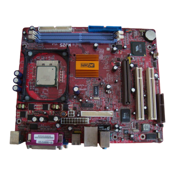
Mainboard User's Manual
This publication, including photographs, illustrations and software,
is under the protection of international copyright laws, with all
rights reserved. Neither this manual, nor any of the material
contained herein, may be reproduced without the express written
consent of the manufacturer.
The information in this document is subject to change without
notice. The manufacturer makes no representations or warranties
with respect to the contents hereof and specifically disclaims any
implied warranties of merchantability or fitness for any particular
purpose. Further, the manufacturer reserves the right to revise this
publication and to make changes from time to time in the content
hereof without obligation of the manufacturer to notify any person
of such revision or changes.
Trademarks
IBM, VGA, and PS/2 are registered trademarks of International
Business Machines.
Intel, Pentium, Pentium-II, Pentium-III, Pentium 4, MMX,
Celeron and Tualatin are registered trademarks of Intel
Corporation.
Microsoft, MS-DOS and Windows 98/ME/NT/2000/XP are
registered trademarks of Microsoft Corporation.
PC-cillin is a trademark of Trend Micro Inc.
AMI is a trademark of American Megatrends Inc.
MediaRing Talk is a registered trademark of MediaRing Inc.
3Deep is a registered trademark of E-Color Inc.
It has been acknowledged that all mentioned brands or product
names are trademarks or registered trademarks of their respective
holders.
Copyright © 2002
All Rights Reserved
M925 Series, V1.3
VT8751/February 2002

Advertisement

Table of Contents
loading
Need help?

Need help?

Do you have a question about the M925 Series and is the answer not in the manual?

Questions and answers

Summary of Contents for PCchips M925 Series

  • Page 1 MediaRing Talk is a registered trademark of MediaRing Inc. 3Deep is a registered trademark of E-Color Inc. It has been acknowledged that all mentioned brands or product names are trademarks or registered trademarks of their respective holders. Copyright © 2002 All Rights Reserved M925 Series, V1.3 VT8751/February 2002...
  • Page 2 Mainboard User’s Manual Notice: Owing to Microsoft’s certifying schedule is various to every supplier, we might have some drivers not certified yet by Microsoft. Therefore, it might happen under Windows XP that a dialogue box (shown as below) pop out warning you this software has not passed Windows Logo testing to verify its compatibility with Windows XP.
  • Page 3: Table Of Contents

    Mainboard User’s Manual Table of Contents Chapter 1: Introduction..............1 Key Features................2 Package Contents..............5 Static Electricity Precautions..........6 Pre-Installation Inspection............6 Chapter 2: Mainboard Installation..........7 Mainboard Components............8 I/O Ports..................9 Installing the Processor............10 Installing Memory Modules..........11 Jumper Settings..............13 The Panel Connectors............15 Other Devices Installation.............17 Expansion Slots Installation..........18 Connecting Optional Devices ..........19 Chapter 3: BIOS Setup Utility............23...
  • Page 4 Mainboard User’s Manual...
  • Page 5: Chapter 1: Introduction

    1: Introduction Chapter 1 Introduction This mainboard has a Socket 478 for the Intel Pentium 4 type of processors supporting front side bus (FSB) speeds up to 400 MHz. This mainboard has the VIA VT8751(P4M266) Northbridge and VT8233 Southbridge chipsets that support AC 97 audio codec, and provide Ultra DMA 33/66/100 function.
  • Page 6: Key Features

    Mainboard User’s Manual Key Features This mainboard has these key features: Socket 478 Processor  The PGA Socket 478  Accommodates Intel Pentium 4 CPUs  Supports a front-side bus (FSB) of 400 MHz Chipset There are VT8751 Northbridge and VT8233 Southbridge in this chipset in accordance with an innovative and scalable architecture with proven reliability and performance.
  • Page 7 1: Introduction Built-in Graphics System  P4M266 integrates S3’s Savag4 graphics accelerator into a single chip. P4M266 brings mainstream graphics performance to the Value PC with leading-edge 2D, 3D and DVD video acceleration into a cost effective package. Based on its capabilities, P4M266 is an ideal solution for the consumer, corporate mobile users and entry level professionals.
  • Page 8 Mainboard User’s Manual  One VGA port  One parallel port  One MIDI/game port  Six USB ports (two backpanel ports, onboard USB headers providing four extra ports)  Audio jacks for microphone, line-in and line-out BIOS Firmware This mainboard uses AMI BIOS that enables users to configure many system features including the following: ...
  • Page 9: Package Contents

    1: Introduction  Language Genius 21 is the software to provides learning tools of language and singing  PC DJ is a dual-MP3 player that enables users to actually mix music right on their own personal computers.  Adobe Acrobat Reader V5.0 is the software to help users read .PDF files.
  • Page 10: Static Electricity Precautions

    Mainboard User’s Manual Static Electricity Precautions Static electricity could damage components on this mainboard. Take the following precautions while unpacking this mainboard and installing it in a system. 1. Don’t take this mainboard and components out of their original static-proof package until you are ready to install them. 2.
  • Page 11: Chapter 2: Mainboard Installation

    2: Mainboard Installation Chapter 2 Mainboard Installation To install this mainboard in a system, please follow these instructions in this chapter: Identify the mainboard components  Install a CPU  Install one or more system memory modules  Make sure all jumpers and switches are set correctly ...
  • Page 12: Mainboard Components

    Mainboard User’s Manual Mainboard Components Identify major components on the mainboard via this diagram underneath. Note: Those jumpers of mainboard not appearing in this illustration are for testing only.
  • Page 13: I/O Ports

    2: Mainboard Installation I/O Ports The illustration below shows a side view of the built-in I/O ports on the mainboard. 1. Upper PS/2 port connects a PS/2 pointing device. 2. Lower PS/2 port connects a PS/2 keyboard. 3. USB ports connect USB devices. LPT1 connects printers or other parallel communications devices.
  • Page 14: Installing The Processor

    Mainboard User’s Manual Installing the Processor This mainboard has a Socket 478 processor socket. When choosing a processor, consider the performance requirements of the system. Performance is based on the processor design, the clock speed and system bus frequency of the processor, and the quantity of internal cache memory and external cache memory.
  • Page 15: Installing Memory Modules

    2: Mainboard Installation Installing Memory Modules This mainboard accommodates 168-pin 3.3V/184-pin 2.5V unbuffered SDRAM memory modules. The memory chips must be standard or registered SDRAM (Synchronous Dynamic Random Access Memory). The CPU supports 100MHz system bus. The SDRAM DIMMs and DDRs can synchronously work with 100 MHz or operates over a 266 MHz system bus.
  • Page 16 Mainboard User’s Manual Installation Procedure The mainboard accommodates two memory modules. You must install at least one module in any of the three slots. Each module can be installed with up to 2GB system memory. Refer to the following to install the memory modules. 1.
  • Page 17: Jumper Settings

    2: Mainboard Installation Jumper Settings PANEL1 JP1A1 JP1B1 JP16 PANEL2 JBAT1 JBAT1: Clear CMOS Jumper This jumper is to clear the contents of CMOS memory. You may need to clear the CMOS memory if the settings in the Setup Utility are incorrect that prevents your mainboard from operating.
  • Page 18 Mainboard User’s Manual JP1: DRAM Voltage (VCC) This jumper enables to select voltage of DRAM. Function Jumper Setting 2.5V (DDR) Open Pins 1-2 (SDR) Short Pins 1-2 J2A/B/C/D, J3A/B/C/D: DDR/SDR DRAM Type Selector This jumper enables to select the type of DDR or SDR DRAM.
  • Page 19: The Panel Connectors

    2: Mainboard Installation The Panel Connector PANEL1 If there are a headphone jack or/and a microphone jack on the front panel, connect the cables to the PANEL1 on the mainboard. Device Pins Line Out (L) 9, 10 Line Out (R) 5, 6 MIC In 1, 2...
  • Page 20 Mainboard User’s Manual J16: LAN LED Indicator This connector is attached to LAN device that needs a LED indicator. Device Pins Link LED 1, +2 LINK ACT LED +3, 4 Note: The plus sign (+) indicates a pin which must be connected to a positive voltage.
  • Page 21: Other Devices Installation

    2: Mainboard Installation Other Devices Installation Floppy Diskette Drive Installation The mainboard has a floppy diskette drive (FDD) interface and ships with a diskette drive ribbon cable that supports one or two floppy diskette drives. You can install a 5.25-inch drive and a 3.5- inch drive with various capacities.
  • Page 22: Expansion Slots Installation

    Mainboard User’s Manual Expansion Slots Installation This mainboard has two 32-bit PCI (Peripheral Components Interconnect) expansion slots, one 4xAGP slot, and one CNR slot. PCI Slots PCI slots are used to install expansion cards that have the 32-bit PCI interface. 4 x AGP Slot The 4xAGP slot is used to install a graphics adapter that supports the 4xAGP specification and has a 4xAGP edge connector.
  • Page 23: Connecting Optional Devices

    2: Mainboard Installation Connecting Optional Devices Refer to the following for information on connecting the mainboard’s optional devices: SIR1 WOM1 WOL1 SPK1 USB1 USB2...
  • Page 24 Mainboard User’s Manual J12: Sleep Switch This header is connected to the sleep button for suspending the computer’s activity if pushing the button. Or, the computer is automatically suspended after passing a period of time. Signal -EXTSMI SPK1: Speaker Connector Connect the cable from the PC speaker to the SPK1 header on the mainboard.
  • Page 25 2: Mainboard Installation If you have installed a modem, use the cable provided with the modem to plug into the mainboard WOM1 connector. This enables the Wake On Modem (WOM1) feature. When your system is in a power-saving mode, any modem signal automatically resumes the system.
  • Page 26 Mainboard User’s Manual SIR1: Serial infrared port The mainboard supports a Serial Infrared (SIR1) data port. Infrared ports allow the wireless exchange of information between your computer and similarly equipped devices such as printers, laptops, Personal Digital Assistants (PDAs), and other computers. Signal Signal IRTX...
  • Page 27: Chapter 3: Bios Setup Utility

    3: BIOS Setup Utility Chapter 3 BIOS Setup Utility Introduction The BIOS Setup Utility records settings and information of your computer, such as date and time, the type of hardware installed, and various configuration settings. Your computer applies those information to initialize all the components when booting up and basic functions of coordination between system components.
  • Page 28: Running The Setup Utility

    Mainboard User’s Manual Running the Setup Utility Every time you start your computer, a message appears on the screen before the operating system loading that prompts you to “Hit <DEL>if you want to run SETUP”. Whenever you see this message, press the Delete key, and the Main menu page of the Setup Utility appears on your monitor.
  • Page 29: Standard Cmos Setup Page

    3: BIOS Setup Utility Standard CMOS Setup Page This page helps you set up basic information such as the date and time, the IDE devices, and the diskette drives. AMIBIOS SETUP – STANDARD CMOS SETUP (C) 2000 American Megatrends, Inc. All Rights Reserved Date (mm/dd/yy) : Tue Feb 26, 2002 Time (hh/mm/ss) : 18:14:00 32Bit...
  • Page 30 Mainboard User’s Manual...
  • Page 31: Advanced Setup Page

    3: BIOS Setup Utility Advanced Setup Page This page sets up more advanced information about your system. Be more careful to this page. Any changes can affect the operation of your computer. AMIBIOS SETUP – ADVANCED SETUP (C) 2000 American Megatrends, Inc. All Rights Reserved Quick Boot Enabled AGP Mode...
  • Page 32 Mainboard User’s Manual S.M.A.R.T. for Enable this item if any IDE hard disks Hard Disks support the S.M.A.R.T. (Self- Monitoring, Analysis and Reporting Technology) feature. BootUp Num- This item determines if the Num Lock Lock key is active or inactive at system start- up time.
  • Page 33 3: BIOS Setup Utility SDRAM Timing This item allows you to enable or disable By SPD the SDRAM timing defined by the Serial Presence Detect electrical. SDRAM This item determines frequency of Frequency SDRAM memory. SDRAM CAS# This item determines the operation of Latency SDRAM memory CAS (column address strobe).
  • Page 34: Power Management Setup Page

    Mainboard User’s Manual Power Management Setup Page This page sets up some parameters of system power management operation. AMIBIOS SETUP – POWER MANAGEMENT SETUP (C) 2000 American Megatrends, Inc. All Rights Reserved ACPI Aware O/S Power Management/APM Disabled Video Power Down Mode Suspend Hard Disk Power Down Mode Standby...
  • Page 35 3: BIOS Setup Utility ACPI Aware This item supports ACPI (Advanced Configuration and Power management Interface). Use this item to enable or disable the ACPI feature. Power Use this item to enable or disable a power Management management scheme. If you enable power management, you can use the items below to set the power management operation.
  • Page 36 Mainboard User’s Manual PowerOn by If you enable this item, system can automatically resume by pressing hot keys Wake up key on the keyboard or typing in the password. Wake up You must enable the Keyboard Power On password jumper and use an ATX power supply in order to use this feature.
  • Page 37: Pci/Plug And Play Setup Page

    3: BIOS Setup Utility PCI / Plug and Play Setup Page This page sets up some parameters for devices installed on the PCI bus and those utilizing the system plug and play capability. AMIBIOS SETUP – PCI / PLUG AND PLAY SETUP (C) 2000 American Megatrends, Inc.
  • Page 38: Load Optimal Settings

    Mainboard User’s Manual Load Optimal Settings If you select this item and press Enter a dialog box appears. If you press Y, and then Enter, the Setup Utility loads a set of fail-safe default values. These default values are not very demanding and they should allow your system to function with most kinds of hardware and memory chips.
  • Page 39: Features Setup Page

    3: BIOS Setup Utility Features Setup Page This page sets up some parameters for those peripheral devices connected to the system. AMIBIOS SETUP – FEATURES SETUP (C) 2000 American Megatrends, Inc. All Rights Reserved OnBoard FDC Disabled OnBoard Serial PortA 3F8h/COM1 OnBoard Serial PortB 2F8h/COM2...
  • Page 40 Mainboard User’s Manual Parallel Port Use this item to set the parallel port mode. Mode You can select SPP (Standard Parallel Port), ECP (Extended Capabilities Port), EPP (Enhanced Parallel Port), or ECP + EPP. Parallel Port Use this item to assign IRQ to the parallel port.
  • Page 41: Cpu Pnp Setup Page

    3: BIOS Setup Utility CPU PnP Setup Page This page helps you manually configure the mainboard for the CPU. The system will automatically detect the type of installed CPU and make the appropriate adjustments to the items on this page. AMIBIOS SETUP –...
  • Page 42: Hardware Monitor Page

    Mainboard User’s Manual Hardware Monitor Page This page sets up some parameters for the hardware monitoring function of this mainboard. AMIBIOS SETUP – HARDWARE MONITOR (C) 2000 American Megatrends, Inc. All Rights Reserved *** System Hardware *** Vcore 1.632V Vcc 2.5V 2.496V Vcc 3.3V 3.392V...
  • Page 43: Change Password

    3: BIOS Setup Utility Change Password If you highlight this item and press Enter, a dialog box appears that you can enter a Supervisor password. You can enter no more than six letters or numbers. Press Enter after you have typed in the password.
  • Page 44 Mainboard User’s Manual...
  • Page 45: Chapter 4: Software & Applications

    4: Software & Applications Chapter 4 Software & Applications Introduction This chapter describes the contents of the support CD-ROM that comes with the mainboard package. The support CD-ROM contains all useful software, necessary drivers and utility programs to properly run our products. More program information is available in a README file, located in the same directory as the software.
  • Page 46: Installing Support Software

    Mainboard User’s Manual Installing Support Software 1.Insert the support CD-ROM disc in the CD-ROM drive. 2.When you insert the CD-ROM disc in the system CD-ROM drive, the CD automatically displays an Auto Setup screen. 3.The screen displays three buttons of Setup, Browse CD and Exit on the right side, and three others Setup, Application and ReadMe at the bottom.
  • Page 47 4: Software & Applications Auto-Installing under Windows 98/ME/2000/XP If you are under Windows 98/ME/2000/XP, please click the Setup button to run the software auto-installing program while the Auto Setup screen pops out after inserting the support CD-ROM: 1. The installation program loads and displays the following screen.
  • Page 48: Bundled Software Installation

    Mainboard User’s Manual Installing under Windows NT or Manual Installation If you are under Windows NT, the auto-installing program doesn’t work out; or you have to do the manual installation, please follow this procedure while the Auto Setup screen pops out after inserting the support CD-ROM: 1.

This manual is also suitable for:

M925lrM922 seriesM922lr v1M922lr v3

Table of Contents