Table of Contents
Advertisement
Advertisement
Table of Contents
Troubleshooting

Related Manuals for STA-RITE IntelliPro Variable Speed


Summary of Contents for STA-RITE IntelliPro Variable Speed
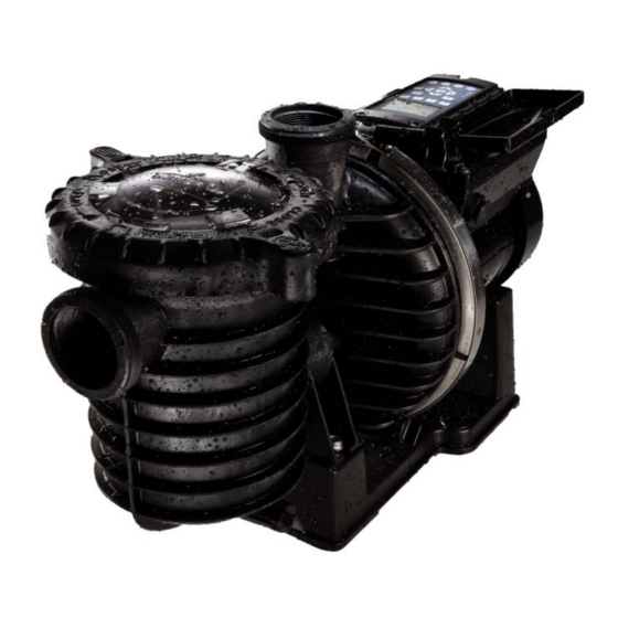
- Page 1 IntelliPro Variable Speed ® Programmable Pump (Compatible with IntelliComm communication center and ® EasyTouch , IntelliTouch and SunTouch control systems) ® ® ® Installation User’s Guide IMPORTANT SAFETY INSTRUCTIONS READ AND FOLLOW ALL INSTRUCTIONS SAVE THESE INSTRUCTIONS...
- Page 2 , Pentair ® ® Water Pool and Spa and Sta-Rite are registered tradmarks and/or trademarks of Pentair Water Pool and Spa, Inc. ® and/or its affi liated companies in the United States and/or other countries. Tefl on is a registered trademark of E.I. Du Pont De Nemours and Company Corporation and Plasto-Joint Stik ®...
-
Page 3: Table Of Contents
Contents Important Warning and Safety Instructions ............iii ® Section 1: IntelliPro Pump Overview ..............1 IntelliPro ® Pump .......................1 External Control .......................1 Features ........................2 ® IntelliPro Drive Assembly and Control Panel ............3 IntelliPro ® Motor Features ..................3 Section 2: Operator Control Panel ..............4 ®... - Page 4 Contents Section 4: User Maintenance ................26 Pump Strainer Basket ....................26 Pump Strainer Basket Service .................26 Motor Service ......................27 Winterizing .......................28 Priming the pump after service ................28 Section 5: Installation and Removal ..............29 ® IntelliPro Variable Speed Kit Contents ..............29 ® Installing the IntelliPro ....................29 Location .......................29...
- Page 5 For Pool and Spa Pumps (Non SVRS Pumps) ® ® ® (Pentair Water Pool and Spa , Sta-Rite , and Pentair Pool Products ® Warnings and safety instructions for Pentair Water Pool and Spa pumps and other related products are available at: http://www.pentairpool.com/pool-owner/safety-warnings/ or call (800) 831-7133 for additional free copies of these...
- Page 6 PUMP WARNING AND SAFETY INSTRUCTIONS For Pool and Spa Pumps (Non SVRS Pumps) (Pentair Water Pool and Spa ® , Sta-Rite ® , and Pentair Pool Products ® THE USE OF UNAPPROVED COVERS OR ALLOWING USE OF THE POOL OR SPA WHEN COVERS ARE MISSING, CRACKED OR BROKEN CAN RESULT IN BODY OR LIMB ENTRAPMENT, HAIR ENTANGLEMENT, BODY ENTRAPMENT, EVISCERATION AND/OR DEATH.
- Page 7 PUMP WARNING AND SAFETY INSTRUCTIONS For Pool and Spa Pumps (Non SVRS Pumps) (Pentair Water Pool and Spa ® , Sta-Rite ® , and Pentair Pool Products ® The Virginia Graeme Baker (VGB) Pool and Spa Safety Act creates new requirements for owners and operators of commercial swimming pools and spas.
- Page 8 ® Pentair Water Pool and Spa PUMP WARNING AND SAFETY INSTRUCTIONS For Pool and Spa Pumps (Non SVRS Pumps) (Pentair Water Pool and Spa ® , Sta-Rite ® , and Pentair Pool Products ® General Installation Information • All work must be performed by a qualifi ed pool professional, and must conform to all national, state, and local codes.
- Page 9 ® Pentair Water Pool and Spa PUMP WARNING AND SAFETY INSTRUCTIONS For Pool and Spa Pumps (Non SVRS Pumps) (Pentair Water Pool and Spa ® , Sta-Rite ® , and Pentair Pool Products ® General Warnings, (Continued). • Never open the inside of the drive motor enclosure. There is a capacitor bank that holds a 230 VAC charge even when there is no power to the unit.
- Page 10 viii Blank Page ® IntelliPro Variable Speed Pump Installation and User’s Guide...
-
Page 11: Pump Overview
Section 1 Pump Overview Introduction ® The IntelliPro Variable Speed pump is well suited for all of your pool, spa, cleaner, waterfall and other ® water applications. Using the control panel, IntelliPro can use one of the four selectable preset speeds ®... -
Page 12: Features
Features Adjusts to various pool sizes Prevents thermal overload Detects and prevents damage from under and over voltage conditions Protects pump against freezing Communicates with a Pentair EasyTouch, IntelliTouch or SunTouch control system or IntelliComm communication center via a two-wire RS-485 cable connection ... -
Page 13: Intellipro Drive Assembly And Control Panel
® IntelliPro Drive Assembly and Control Panel ® The IntelliPro drive assembly consists of an operator control panel and the system electronics that drive the motor. The drive microprocessor controls the motor by changing the frequency of the current it receives together with changing the voltage to control the rotational speed. Communication port for connection to EasyTouch, IntelliTouch or SunTouch Operator Control Panel,... -
Page 14: Section 2: Operator Control Panel
Section 2 Operator Control Panel ® This section describes the IntelliPro Variable Speed pump operator controls and LEDs. ® IntelliPro Operator Control Panel 12:15 750 RPM 750 RPM T 0.00 150 WATTS Running Speed 1 Speed Speed Speed Speed Time Quick Clean Controls and LEDs... - Page 15 Line 1 12:15 750 RPM 750 RPM Line 2 Line 3 T 0.00 WATTS Running Speed 1 Line 4 Speed Speed Speed Speed Quick Time Clean 15.W Arrow buttons: • Up arrow: Move one level up in the menu tree or increase a digit when editing a setting. •...
-
Page 16: Section 3: Operating The Pump
Section 3 Operating the IntelliPro Pump ® This section describes how to operate the IntelliPro Variable Speed pump using the control panel buttons and menu features. Starting the pump To start the pump 1. Be sure the pump is powered on and the green power LED is on. 2. -
Page 17: Pump Operating Modes
Pump Operating Modes ® The IntelliPro Variable Speed pump can be programmed three ways: 1. Manual Operation: Speed buttons 1-4 can be programmed for Manual operation. This means the speed button is pressed and then the start button and the pump runs a programmed speed. Speeds 5-8 can not be programmed for Manual operation because there are no buttons associated with them. -
Page 18: Intellipro Variable Speed Pump Menus
® IntelliPro Variable Speed Pump Menus Press MENU button to access menus MAIN SCREEN SETTINGS (1-16) Default: ADDRESS 1 Pump Address (page 9) Set Time (hr:mm) Default: 12:00 AM AM/PM Set AM/PM 24 hr. Temperature Unit Fahrenheit - Default: F° C°... -
Page 19: Settings: Pump Address
IntelliPro ® Pump Menus ® The IntelliPro pump menu descriptions are as follows: Settings: Pump Address ® The pump address needs to be changed when there is more than one IntelliPro pump on an automation system. Addressing the pump allows the automation system to know which pump to send a command ®... -
Page 20: Settings: Set Am/Pm Or 24 Clock
Settings: Set AM/PM or 24 Hour Clock This setting is for changing the pump’s time clock from regular time (AM/PM) to a 24 hour clock. For example, Midnight (12:00 AM) is 0000 hr., 8:00 AM is 0800 hr., and 11:00 PM is 2300 hr. To access the AM/PM or 24 hr. -
Page 21: Settings: Language
Settings: Language To access the language menu: 1. Check that the green power LED is on. 2. Press the Menu button. “Settings” is displayed. 3. Press the Select button. “Pump Address” is displayed. 4. Use the Up or Down arrow button to scroll to “Language”. 5. -
Page 22: Settings: Password
Settings: Password When the Password feature is enabled, the pump will enter into password protection mode for a pre programmed amount of time after the last button is pressed. The entered password is any combination of four (4) digits. To access the Password menu: 1. -
Page 23: Password Protection
Password Protection Password: The default for this setting is disabled, which means the pump does not have password protection. When this feature is enabled, for a preset amount of time after the last button is pressed, the pump’s display will prompt for the password before allowing access to the pump’s control panel and buttons The password must be a four (4) numeric digit password. -
Page 24: Speed 1-8 (Schedule A Time To Run The Pump)
Speed 1-8 (Schedule a Time to Run the Pump) By setting a start time and a stop time, Speeds 1-8 can be programmed to run a certain speed at a certain time of day. To run a scheduled pump speed, press the Start button (LED on). The LCD screen will display “Running Schedules”... -
Page 25: External Control
Programming for Constant Run When programming a schedule for a speed, the speed can not be programmed with the same start and stop times. However, it will run without stopping if it is programmed with the start time set one minute after the stop time. -
Page 26: Features: Time Out
Quick Clean (Continued) To access the Quick Clean menu: 1. Check that the green power LED is on. 2. Press the Menu button. “Settings” is displayed. 3. Use the Down arrow button to scroll to “Features”. 5. Press the Select button. “Timeout” is displayed. 6. -
Page 27: Priming
Priming The default setting for Priming is ENABLED. Enabling this feature allows the pump to use its “Flow Technology” to make sure the pump is primed when it starts. This feature will not override the “Max Speed” setting. The priming feature ramps the pump to 1800 RPM and pauses for three (3) seconds. If there is suffi... - Page 28 Priming (Continued) To access the Priming menu: 1. Check that the green power LED is on and press the Menu button. “Settings” is displayed. 2. Use the Down arrow button to scroll to “Priming” 3. Press the Select button. The factory default is set to priming “Enabled“. 4.
-
Page 29: Antifreeze
To disable the priming feature on the pump and let automation system control the pump: 1. Open the lid on the LCD screen of the pump. 2. Verify the green power LED is on. Press the MENU button. Settings is displayed. 3. -
Page 30: Priming The Pump For The Fi Rst Time, Or After Service
Priming the pump for the fi rst time, or after service ® The IntelliPro must be primed before starting the pump for the fi rst time. To prime a pump means fi lling the pump and suction pipe with water. This process evacuates the air from all the suction lines and the pump. -
Page 31: Priming The Pump
Priming the pump for the fi rst time, or after service (Continued) Priming the Pump If you replace the o-ring with a non-lubricated o-ring, you may need to apply a silicone NOTICE: based lubricant. • Clean and inspect o-ring; reinstall on trap cover. •... -
Page 32: External Control With Intellicomm Communication Center
® External Control with IntelliComm Communication Center ® The IntelliPro pump can be remotely controlled by the Pentair Water Pool and Spa IntelliComm Communication Center using a RS-485 communications cable (P/N 350122). The IntelliComm provides four pairs of input terminal connections. These inputs are actuated by either ®... -
Page 33: Connecting The Pump To Easytouch And Intellitouch Systems
® ® ® Connecting IntelliPro to EasyTouch and IntelliTouch System ® The IntelliPro pump can be controlled by an EasyTouch or IntelliTouch automation system via the RS-485 communication cable (P/N 350122). In this confi guration, EasyTouch/IntelliTouch starts, stops ® and controls the speed of the IntelliPro pump. - Page 34 ® ® ® Connecting IntelliPro to EasyTouch and IntelliTouch System (Continued) 7. Strip back the cable conductors 6 mm (1/4”). Insert the two wires into the COM port screw terminals on the EasyTouch/IntelliTouch circuit board. Secure the wires with the screws. 8.
-
Page 35: Connecting The Pump To A Suntouch System
® ® Connecting the IntelliPro pump to a SunTouch System ® The IntelliPro pump can be controlled by a SunTouch system via the RS-485 communication cable. WARNING - Switch OFF main system power to the SunTouch Power Center before making any connections. ®... -
Page 36: Section 4: User Maintenance
Section 4 User Maintenance ® The following information describes how to service and maintain the IntelliPro Variable Speed pump. Pump Strainer Basket The strainer, sometimes referred to as the “Hair and Lint Pot,” is in front of the of the pump. Inside there is a basket which must be kept clean of leaves and debris at all times. -
Page 37: Motor Service
Pump Strainer Basket Service (Continued) 10. Ensure that the lid o-ring is properly placed. Seat the clamp and lid then turn clockwise until the handles are horizontal as shown. 11. Reconnect the communication cable to the pump if required. 12. Switch the power ON at the circuit breaker. Reset the pool time clock to the correct time. Clamp WARNING FILTER OPERATES UNDER HIGH PRESSURE. -
Page 38: Winterizing
Winterizing ® To protect the IntelliPro pump electronics from damage due to freezing conditions, the pump will switch itself on to generate internal heat when the air temperature drops below 4.4° C (40° F). The ® IntelliPro pump “Anti Freeze” feature is not intended to protect the system plumbing from freezing. The Anti Freeze temperature feature is adjustable and can be changed from 4.4°... -
Page 39: Section 5: Installation And Removal
Section 5 Installation and Removal ® The following information describes how to install the IntelliPro pump. ® Installing the IntelliPro Pump ® Only a qualifi ed service person should install the IntelliPro pump. Refer to “Important Warning And Safety Instructions” on pages iii to vii for additional installation guidance and safety information. ®... -
Page 40: Wiring The Intellipro ® Pump
® Wiring the IntelliPro Pump ® To connect the IntelliPro pump to an AC power source: 1. Make sure all electrical breakers and switches are turned off before wiring motor. 2. Make sure that the wiring voltage is 230 VAC ± 10%. 3. -
Page 41: Pump Disassembly
Pump Disassembly/Removing Old Seal WARNING Always disconnect power to the pool pump at the circuit breaker and disconnect the communication — cable before servicing the pump. Failure to do so could result in death or serious injury to serviceman, pool users or others due to electric shock. Read all servicing instructions before working on the pump. -
Page 42: Shaft Seal Replacement
Shaft Seal Replacement The Shaft Seal consists primarily of two parts, a rotating member and a ceramic seal. The pump requires little or no service other than reasonable care, however, a shaft seal may occasionally become damaged and must be replaced. Note: The polished and lapped faces of the seal can be damaged if not handled with care. -
Page 43: Drive Assembly Removal And Installation
Drive Assembly Removal and Installation WARNING To avoid dangerous or fatal electrical shock hazard, switch OFF power to motor before working on pump or motor. ® To remove the IntelliPro drive assembly and control panel from the pump’s motor assembly: 1. -
Page 44: Section 6: Troubleshooting
Section 6 Troubleshooting ® Use the following general troubleshooting information to resolve possible problems with your IntelliPro pump. Note: Turn off power to unit prior to attempting service or repair. Alerts and Warnings ® The IntelliPro pump displays all alarms and warnings on the control panel display. When an alarm or warning condition exists, the corresponding LED will be lit on the display. -
Page 45: General Intellipro Troubleshooting Problems
® General IntelliPro Troubleshooting Problems Problem Possible Cause Corrective Action Pump failure. Pump will not prime - Air leak in suction. Check suction piping and valve glands on any suction PRIME ERROR may be displayed. gate valves. Secure lid on pump strainer pot and be (For IntelliPro alert display sure lid gasket is in place. - Page 46 ® General IntelliPro Troubleshooting Problems (Continued) Problem Possible Cause Corrective Action Inadequate circulation. Filter or pump basket dirty. Check trap basket; if plugged, turn pump off and (For IntelliPro alert display clean basket. messages, refer to Alerts and Check and clean pool fi lter. Warnings on page 34).
-
Page 47: Section 7: Replacement Parts
Section 7 Replacement Parts Illustrated Parts List 18 10 Box A Pkg. 188 2” Slip Union Kit: (Included with the pump) U11-200PS Union Collar (2) 24 23 U9-362 O-Ring (2) U11-196PS 2” Slip Adapter (2) 17 27 Pkg. 189 2” NPT Adapter Kit:*** U11-200PS Union Collar (2) 20 32 33... -
Page 48: Intellipro Pump Dimensions
® IntelliPro Pump Dimensions 11 1/8 26 1/4 11 7/16 14 1/2 14 1/2 10 3/4 IntelliPro ® Flow Pump Performance Curve ® IntelliPro Electrical Specifi cations Circuit Protection: Two-pole 20 AMP device at the Electrical Panel. Input: 230 VAC, 50/60 Hz, 3200 Watts ®... - Page 49 NOTES...
- Page 50 NOTES...
- Page 51 NOTES...
- Page 52 *354832* Literature Package P/N 354832 Rev A *354831* Manual P/N 354831 Rev A 6/15/11...
Need help?
Do you have a question about the IntelliPro Variable Speed and is the answer not in the manual?
Questions and answers