Table of Contents
Advertisement
Quick Links
DURA-GLAS II
Sta-Rite Pool/Spa Group
600 S. Jefferson Street, Waterford, WI 53185
North America: 800-752-0183, FAX 800-582-2217
International: 414-728-5551, FAX: 414-728-4461, TELEX: ITT 4970245
Oxnard, CA • Union City, TN • Delavan, WI • Waterford, WI • Mississauga, Ont.
© 1996, Sta-Rite Industries, Inc.
TM
WITH INTEGRAL TRAP
O
W N E R '
INSTALLATION, OPERATION & PARTS
P4RA Series MODELS
1-1/2 HP
2 HP
H/L 2-SPEED PUMPS
S
M
A
N
P4RA6YF-151L
P4RA6YG-152L
Printed in U.S.A.
U
A
L
This manual should be furnished to
the end user of this pump; its use will
reduce service calls and chance of
injury and will lengthen pump life.
S295 (Rev. 2/26/96)
Advertisement
Table of Contents

Related Manuals for STA-RITE DURA-GLAS II P4RA Series


Summary of Contents for STA-RITE DURA-GLAS II P4RA Series
- Page 1 600 S. Jefferson Street, Waterford, WI 53185 North America: 800-752-0183, FAX 800-582-2217 International: 414-728-5551, FAX: 414-728-4461, TELEX: ITT 4970245 Oxnard, CA • Union City, TN • Delavan, WI • Waterford, WI • Mississauga, Ont. © 1996, Sta-Rite Industries, Inc. Printed in U.S.A. S295 (Rev. 2/26/96)
-
Page 2: Table Of Contents
To avoid unneeded service calls, prevent possible injuries, and get the most out of your pump, READ THIS MANUAL CAREFULLY! The Sta-Rite ‘P4R’ and ‘P4RA’ Series II 2-speed pumps: • Are designed for use with swimming pools or as centrifugal pumps. -
Page 3: Safety Instructions
• Check all clamps, bolts, lids, and system accessories before testing. • Release all air in system before testing. • Tighten Sta-Rite trap lids to 30 ft. lbs. (4.1 kg-m) torque for testing. • Water pressure for test must be less than 25 PSI (7.5 kg/cm •... -
Page 4: Installation
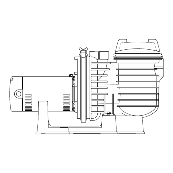
Figure 1 INSTALLATION Only qualified, licensed personnel should install pump and wiring. Pump mount must: Be solid - Level - Rigid - Vibration free. (To reduce vibration and pipe stress, bolt pump to mount.) Allow pump suction inlet height to be as close to water level as possible. Allow for fresh air ventilation. - Page 5 Piping: Use at least 2" IPS PVC (51mm) pipe. Increase size if a long run is needed. To avoid strains on the pump, support both suction and discharge pipes inde- pendently. Place these supports near the pump. To avoid a strain left by a gap at the last connection, start all piping at the pump and run pipe away from the pump.
-
Page 6: Electrical
ELECTRICAL Ground motor before connecting to electrical power supply. Failure to ground motor can cause severe or fatal electrical shock hazard. Do not ground to a gas supply line. To avoid dangerous or fatal electrical shock, turn OFF power to motor before working on electrical connections. -
Page 7: Operation
OPERA TION NEVER run pump dry. Running pump dry may damage seals, causing leakage and flooding. Fill pump with water before starting motor. Before removing trap cover: 1. STOP PUMP before proceeding. 2. CLOSE GATE VALVES in suction and discharge pipes. 3. -
Page 8: Storage/Winterizing
Draining Pump 1. Pump down water level below all inlets to the pool. To avoid dangerous or fatal electrical shock hazard, turn OFF power to motor before draining pump. 2. Remove trap cover and use low pressure air to blow accumulated water from the piping system. -
Page 9: Pump Service
PUMP SERVICE Pump should only be serviced by qualified personnel. Be sure to prime pump (Pg. 7) before starting. Before removing clamp or trap cover: 1. STOP PUMP before proceeding. 2. CLOSE GATE VALVES in suction and discharge pipes. 3. RELEASE ALL PRESSURE from pump and piping system. 4. - Page 10 Pump Reassembly/Installing New Seal 1. Ceramic seat must be clean and free of dirt, grease, dust, etc. Wet outer edge of “O” Ring with small amount of liquid detergent; press ceramic seat into heat sink insert firmly and squarely with finger pressure (Fig. 5). 2.
-
Page 11: Troubleshooting Guide
NOTICE: To prevent leaks around seal, do not install “O” Ring by mounting on heat sink insert and then pushing insert into seal plate cav- ity. “O” Ring will roll out of position and leak if it is mounted on insert first. - Page 12 P4RA SERIES DURA-GLAS II POOL PUMP H/L 2 -SPEED 1-1/2 AND 2 H.P. MODELS 235 0893...
-
Page 13: Repair Parts List
REPAIR PARTS LIST Part Part Description Qty. Motor Chart at Right Screw #10-32 x 1/2” U30-692SS Bonding Lug U17-568 Water Slinger C69-2 Seal Plate C203-187P “O” Ring U9-376 “O” Ring U9-228A Insert C3-186 Screw #8-32 x 1/4” U30-401SS Shaft Seal U109-372SS Impeller Chart at Right... -
Page 15: Warranty
Retain Warranty Certificate (upper portion) in a safe and convenient location for your records. DETACH HERE: Fill out bottom portion completely and mail within 10 days of purchase/installation to: Sta-Rite, Attn: Warranty Dept., 600 S. Jefferson St., Waterford, WI 53185 Warranty Registration Card...
Need help?
Do you have a question about the DURA-GLAS II P4RA Series and is the answer not in the manual?
Questions and answers