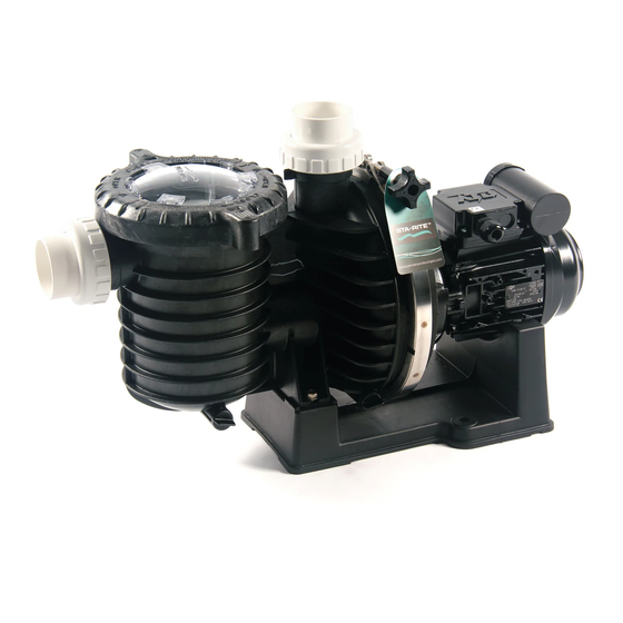
STA-RITE 5P6R Series Owner's Manual
50 hz. max-e-pro centrifugal pumps with integral trap
Hide thumbs
Also See for 5P6R Series:
- Installation and user manual (29 pages) ,
- Installation and user manual (25 pages)
Advertisement
50 HZ. MAX-E-PRO
Sta-Rite Industries, Export Sales & Marketing Group
293 Wright Street, Delavan, WI 53115 U.S.A.
TELEPHONE: (262) 728-5551, TELEFAX: (262) 728-4461, CABLE: STAREX TELEX: ITT 4970245
Printed in U.S.A.
TM
WITH INTEGRAL TRAP
O
W
N
E
R '
INSTALLATION, OPERATION & PARTS
5P6R Series MODELS
HP
1 Phase
3/4
5P6R6D-209
1
5P6R6E-210
1-1/2
5P6R6F-211
2
5P6R6G-212
3
5P6R6H-213
CENTRIFUGAL PUMPS
S
M
A
N
U
3 Phase
5P6R6D3-209
5P6R6E3-210
5P6R6F3-211
5P6R6G3-212
5P6R6H3-213
A
L
This manual should be furnished to
the end user of this pump; its use will
reduce service calls and chance of
injury and will lengthen pump life.
S764 (8/13/04)
Advertisement

Related Manuals for STA-RITE 5P6R Series


Summary of Contents for STA-RITE 5P6R Series
- Page 1 Sta-Rite Industries, Export Sales & Marketing Group 293 Wright Street, Delavan, WI 53115 U.S.A. TELEPHONE: (262) 728-5551, TELEFAX: (262) 728-4461, CABLE: STAREX TELEX: ITT 4970245 S764 (8/13/04) Printed in U.S.A.
-
Page 2: Table Of Contents
Remove trap lid and Troubleshooting Guide ..........10 retighten hand tight only. Repair Parts List ............11-14 NOTICE: These parameters apply to Sta-Rite equipment only. For non-Sta-Rite equipment, consult manufacturer. READ AND FOLLOW SAFETY INSTRUCTIONS! IMPORTANT SAFETY This is the safety alert symbol. -
Page 3: Installation
Fire and burn hazard. Modern motors run at Discharge Port Strainer Basket to filter cover high temperatures. To reduce the risk of fire, do not allow or pool Clamp leaves, debris, or foreign matter to collect around the Knob pump motor. To avoid burns when handling the motor, let it cool for 20 minutes before trying to work on it. - Page 4 POOL PUMP SUCTION Outlets Per Pump REQUIREMENTS Provide at least two hydraulically balanced main drains, with covers (see below), for each swimming pool pump suction line. The centers of the main drains (suction fit- Pump suction is hazardous and can trap tings) must be at least three feet apart.
-
Page 5: Electrical
ELECTRICAL Bonding Ground motor before Motor Nameplate connecting to electrical Green Ground power supply. Failure to Screw ground motor can cause se- Motor vere or fatal electrical shock Canopy hazard. Do not ground to a gas Through supply line. Bolts 349 0893 To avoid dangerous or Figure 3: Typical ground screw and bonding lug locations. - Page 6 To Wire a Single Speed, Single Voltage Motor 1. If you have 230 volts motor supply voltage, confirm that the plug is set for 230 volts. The arrow on the plug Remove the motor end cover. will point to the 230 volt position. Note that plug only There are two terminals labeled L1 and L2.
-
Page 7: Operation
OPERA TION If pump is not in a flooded suction system, remove trap cover handle ring and trap cover; fill trap and pump with NEVER run pump dry. Running pump dry may water. damage seals, causing leakage and flooding. Fill Do not lubricate the trap cover O-Ring. -
Page 8: Storage/Winterizing
Draining Pump 3. Enclose entire system in a weatherproof enclosure. 4. To avoid condensation/corrosion damage, allow venti- 1. Pump down water level below all inlets to the pool. lation; do not wrap system in plastic. To avoid dangerous or 5. Use a 40% propylene glycol/60% water solution to fatal electrical shock protect pump to -50°F (-46°C). - Page 9 If shaft seal is worn or damaged, repair as follows: Pump Reassembly/Installing New Seal 1. Ceramic seat must be Pump Disassembly/Removing Old Seal clean and free of dirt, Disconnect power to pump motor. grease, dust, etc. Wet outer edge of rubber cup Be sure gate valves on suction and return piping are on ceramic seat with closed before starting work.
-
Page 10: Troubleshooting Guide
TROUBLESHOOTING Electrical: GUIDE 9. Pump may be running too slowly; check voltage at Read and understand safety and operating instruc- motor terminals and at tions in this manual before doing any work on meter while pump is run- pump! ning. If low, see wiring in- structions or consult Only qualified personnel should electrically test power company. -
Page 11: Repair Parts List
5P6R SERIES 50 Hz. MAX-E-PRO POOL PUMP 3/4 and 1 HP See Box A See Box A 4285 1102 REPAIR PARTS LIST Part Part Box A Description Qty. Motor Chart at Right For quick disconnect pipe connections, purchase separately: #10-32 x 1/2” Screw U30-692SS Pkg. - Page 12 5P6R SERIES 50 Hz. MAX-E-PRO POOL PUMP 1-1/2 and 2 HP See Box A See Box A 4285 1102 REPAIR PARTS LIST Part Part Description Qty. Motor Chart at Right Box A #10-32 x 1/2” Screw U30-692SS Bonding Lug U17-568...
- Page 13 Model 5P6R6H-213 and 5P6R6H3-213 MAX-E-PRO POOL PUMP 3 HP See Box A See Box A REPAIR PARTS LIST 4285 1102 Part Part Description Qty. Motor 230V/50H/1 Ph (5P4R6H) 62003-2077 Motor 220-240/380-415V/50H 3 Ph (5P4R6H3) 62003-2078 Box A #10-32 x 1/2” Screw U30-692SS Bonding Lug U17-568...
- Page 14 TYPICAL A.O. SMITH MOTOR EXPLODED VIEW 115/230V 50Hz 1ph 230V 50Hz 1ph 220-240/380-415V 50 Hz 3ph Item J218-574A J218-575A J218-864A 62001-1004 62001-1008 J218-815A J218-816A J218-817A 62001-1005 62001-1009 Description 3/4 HP 1 HP 1-1/2 HP 2 HP 3 HP 3/4 HP 1 HP 1-1/2 HP 2 HP...
Need help?
Do you have a question about the 5P6R Series and is the answer not in the manual?
Questions and answers