
Related Manuals for STA-RITE INTELLIPRO 2 VST


Summary of Contents for STA-RITE INTELLIPRO 2 VST
- Page 1 ® INTELLIPRO 2 VST VARIABLE SPEED PUMP INSTALLATION AND USER’S GUIDE IMPORTANT SAFETY INSTRUCTIONS READ AND FOLLOW ALL INSTRUCTIONS SAVE THESE INSTRUCTIONS...
-
Page 2: Table Of Contents
CUSTOMER SERVICE / TECHNICAL SUPPORT If you have questions about ordering Pentair Aquatic Systems replacement parts, and pool products, please contact: Customer Service and Technical Support, USA Sanford, North Carolina (8 A.M. to 4:30 P.M. ET) (8 A.M. to 4:30 P.M. — Eastern/Pacific Times) Phone: (919) 566-8000 Phone: (800) 831-7133 Fax: (919) 566-8920... -
Page 3: Important Pump Warning And Safety Instructions
IMPORTANT PUMP WARNING AND SAFETY INSTRUCTIONS General Warnings • Never open the inside of the drive motor enclosure. There is a IMPORTANT NOTICE capacitor bank that holds a 230 VAC charge even when there is no This guide provides installation and operation instructions for this pump. power to the unit. - Page 4 IMPORTANT PUMP WARNING AND SAFETY INSTRUCTIONS Mechanical Entrapment: When jewelry, swimsuit, hair decorations, HAZARDOUS PRESSURE: STAND CLEAR OF finger, toe or knuckle is caught in an opening of an outlet or drain cover. PUMP AND FILTER DURING START UP This hazard is present when the drain cover is missing, broken, loose, Circulation systems operate under high pressure.
-
Page 5: Pump Overview
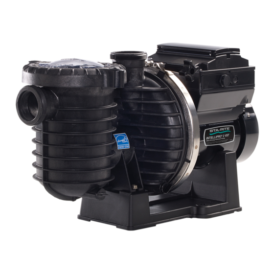
Designed to withstand outdoor environment • Totally Enclosed Fan Cooled (TEFC) Motor, IPX5 Drive Assembly and Control Panel Rated The IntelliPro 2 VST pump drive is designed to produce • Three-phase motor maximum motor operational efficiency. The drive • 56 Square Flange controls the motor’s rotational speed by controlling the... -
Page 6: Installation
When installing the inlet and outlet fittings In special cases when the user lacks easy or (male adaptors), unless using the unions supplied with the convenient access to the IntelliPro 2 VST Variable pump, use thread sealant. Speed Pump, a Keypad Relocation Kit (P/N 356905Z) 2. -
Page 7: Electrical Installation
Electrical Installation RISK OF ELECTRICAL SHOCK OR ELECTROCUTION. This pump must be installed by a licensed or certified electrician or a qualified service professional in accordance with the National Electrical Code and all applicable local codes and ordinances. Improper installation will create an electrical hazard which could result in death or serious injury to users, installers, or others due to electrical shock, and may also cause damage to property. -
Page 8: Operating The Pump
OPERATING THE PUMP NOTE: Speed 1 is the default filtration speed. NOTE: When setting up the IntelliPro ® 2 VST Variable Speed Pump, the user must set the pump’s internal clock and establish an operation schedule by following the steps in this manual. Please refer to user’s guide sections: ‘Set Time’ (page 8) and ‘Set Speeds 1-8 in Schedule Mode’... -
Page 9: Using The Operator Control Panel
Using the Operator Control Panel Use the operator control panel to start and stop the IntelliPro ® VST Variable Speed Pump, program, set, and change speeds (RPM), and access pump features and settings. Controls and LEDs on Keypad: 12:15p Button 1: Press to select Speed 1 (750 RPM). LED on 750 RPM indicates Speed 1 is active. -
Page 10: Stopping And Starting The Pump
Stopping and Starting the Pump Manual Speed 1 (1-4) Set Speed - Defa Starting the Pump Schedule Set Speed 1. Be sure the pump is powered on and the green Set Start Time Set Stop Time power LED is on. Egg Timer Set Speed 2. -
Page 11: Control Panel: Pump Menu Guide
Operator Control Panel: Pump Menu Guide MENU Press MENU button to access menus SETTINGS Set Date and Time Date Months (1-12) Days (1-31) (pages 8-10) Years (2000-2050 Plus) Time Hours (24hr Mode: 0-23) (12hr Mode: 1-12 AM & PM) Minutes (0-60) Hour Format AM/PM - Default: AM/PM 24 Hour... -
Page 12: Pump Settings
Set Minimum Speed (RPM) can communicate to only four (1-4) pumps. The minimum pump speed can be set from 450 RPM Note: IntelliPro 2 VST pumps cannot be connected in to 1700 RPM. The default setting is 450 RPM. series with other pumps. -
Page 13: Set Screen Contrast
MENU Pump Menu: Settings SETTINGS Pump Address (cont.) Set Temperature Unit 5. Use the Up or Down arrows to scroll to “Pump The default setting is Fahrenheit (°F). The pump can be Address” and press Select. set to either Celsius (°C) or Fahrenheit (°F). 6. -
Page 14: Setting Password
MENU MENU Pump Menu: Settings SPEED 1-8 Pump Menu: Speeds 1-8 SETTINGS Pump Operating Modes Setting Password 1. Check that the green power LED is on. ® The IntelliPro 2 VST Variable Speed Pump can be programmed in three different modes: 2. -
Page 15: Setting Speeds 1-8
MENU SPEED 1-8 Pump Menu: Speeds 1-8 Set Speeds in Manual Mode Set Speeds 1-8 in Schedule Mode (Speeds 1-4 Only) In Schedule mode, Speeds 1-8 can be programmed 1. Press Menu. to run a certain speed at a certain time of day. To run a scheduled speed, press Start/Stop. -
Page 16: External Control
MENU MENU Pump Menu: External SPEED 1-8 Pump Menu: Speeds 1-8 EXT CONTROL Control Set Speeds 1-8 in Schedule Mode (cont.) External Control This function is for programming speeds that will run Programming Schedule for Constant Run ® when the IntelliComm Communication Center sends A speed cannot be programmed with the same start it a command. -
Page 17: Features
MENU 10. Press Select to change the time. The cursor will highlight the minutes column. Pump Menu: Features FEATURES 11. Use Up or Down arrows to change the time from 1 minute to 10 hours. Time Out 12. Press Save to save the time. The Time Out feature keeps the pump from running it’s 13. -
Page 18: Priming Features
MENU PRIMING Pump Menu: Priming Priming Features Default: ENABLED DISABLED/ENABLED Allows IntelliPro ® 2 VST Variable Speed Pump to automatically detect if pump if is primed for startup. The pump will speed up to 1800 RPM and pause for three (3) seconds - if there is enough water in the basket, the pump will go out of priming mode and run the commanded speed. -
Page 19: Setting Priming Features
MENU PRIMING Pump Menu: Priming Setting Priming Features Disabling Priming with an Automation System Note: Priming features are only accessible if priming is “Enabled”. When the IntelliPro ® 2 VST Variable Speed Pump is connected to an automation control system, 1. -
Page 20: Thermal Mode
MENU Pump Menu: Thermal Mode THERMAL MODE The sensor for Thermal Mode is in the drive, on top of To Set Thermal Mode Speed and Pump Temperature: the motor. This feature allows you to set a speed (450 Note: Thermal Mode features are only accessible if ®... -
Page 21: Connecting To An Automation System
CONNECTING TO AN AUTOMATION SYSTEM ® Wiring Terminal Descriptions for IntelliComm External Control with IntelliComm Communication Center Communication Center Use the RS-485 communications cable to remotely Terminal Terminal Max. Phase ® control the IntelliPro 2 VST Variable Speed Pump Voltage Frequency Number Name... - Page 22 To connect the IntelliPro ® 2 VST Variable Speed ® Pump communication cable to EasyTouch ® IntelliTouch Control System load center: 1. Switch the main power off to the load center. IntelliTouch COM port (J7/8): Connect the GREEN (#2) and YELLOW (#3) wires to the COM port (J20) 2.
-
Page 23: Connecting To Suntouch Systems
® Connecting to a SunTouch Control System The IntelliPro ® 2 VST Variable Speed Pump can be Switch OFF main system power to the SunTouch controlled by a SunTouch system via the RS-485 system power center before making any communication cable. connections. -
Page 24: Maintenance
MAINTENANCE DO NOT open the strainer pot if the IntelliPro ® 2 VST Variable Speed Pump fails to prime or if pump has been operating without water in the strainer pot. Pumps operated in these circumstances may experience a build up of vapor pressure and may contain scalding hot water. -
Page 25: Servicing
SERVICING ® Always disconnect power to the IntelliPro 2 VST Variable Speed Pump at the circuit breaker and disconnect the communication cable before servicing the pump. Failure to do so could result in death or serious injury to service people, users or others due to electric shock. -
Page 26: Pump Reassembly/Installing New Seal
Pump Reassembly/Installing New Seal 1. Clean the ceramic seat of dirt, grease, dust, etc. 10. Reconnect the RS-485 communication cable to the pump. Wet the outer edge of the rubber cup on the ceramic 11. Fill the pump with water. seat with water. -
Page 27: Alerts And Warnings
Drive Assembly Removal and Alerts and Warnings Installation, (continued) ® The IntelliPro 2 VST Variable Speed Pump displays all alarms and warnings on the control panel display. When Before installing this product, read and follow all an alarm or warning condition exists, the corresponding warning notices and instructions on page ii - iii. -
Page 28: Troubleshooting
TROUBLESHOOTING ® Always disconnect power to the IntelliPro 2 VST Variable Speed Pump at the circuit breaker and disconnect the communication cable before servicing the pump. Failure to do so could result in death or serious injury to serviceman, pool users or others due to electric shock. - Page 29 Troubleshooting, Continued Problem Possible Cause Corrective Action Electrical problem. Could appear as a “Low Voltage” alarm. Check voltage at motor terminals and at panel while pump is running. If low, see wiring instructions or (For alert display consult power company. messages, refer to Alerts and Warning on page 23).
-
Page 30: Replacement Parts
TRAP COVER ASSEMBLY O-RING C103-194P SEAL PLATE 350122 50 FT. COMMUNICATION CABLE 17351-0101S SHAFT SEAL, EPDM BLACK 354045 POWER END INTELLIPRO 2 VST C105-238PLA IMPELLER ASSEMBLY Note: (*) Items not shown 37007-6080 IMPELLER SCREW C1-271P DIFFUSER U43-21SS #8 EXT TOOTH WASHER (Qty. 5) ®... -
Page 31: Pump Dimensions
Pump Dimensions 26.1 11.4 14.2 10.8 17.1 14.6 Electrical Specifications Circuit Protection: Two-pole 20 AMP device at the Electrical Panel. Input: 208-230 VAC, 50/60 Hz, 3200 Watts Maximum, 1 phase Pump Performance Curves MAX SPEED - 3450 RPM SPEED 4 - 3110 RPM SPEED 3 - 2350 RPM SPEED 2 - 1500 RPM SPEED 1 - 750 RPM... -
Page 32: Operator Control Panel Quick Reference Guide
Operator Control Panel: Pump Menu Quick Reference Guide MENU Press MENU button to access menus SETTINGS Set Date and Time Date Months (1-12) Days (1-31) (pages 8-10) Years (2000-2050 Plus) Time Hours (24hr Mode: 0-23) (12hr Mode: 1-12 AM & PM) Minutes (0-60) Hour Format AM/PM - Default: AM/PM... - Page 33 NOTES...
- Page 34 NOTES...
- Page 35 NOTES...
- Page 36 10951 WEST LOS ANGELES AVE., MOORPARK, CA 93021 • (805) 553-5000 WWW.PENTAIRPOOL.COM ® ® ® ® All Pentair trademarks and logos are owned by Pentair, Inc or one of its global affiliates. Pentair Aquatic Systems , Sta-Rite , IntelliPro , IntelliComm ® ® ® ®...
Need help?
Do you have a question about the INTELLIPRO 2 VST and is the answer not in the manual?
Questions and answers
I am getting a “clear drain” alert. What drain is this referring too?