
Related Manuals for Atmel ATZB-EVB-24-SMA


Summary of Contents for Atmel ATZB-EVB-24-SMA
- Page 1 ZigBit Development Kits ATZB-EVB-24-SMA, ATZB-EVB-900-SMA, ZigBit ATZB-EVB-A24-SMA, ATZB-EVB-24-PCB, Development Kits ATZB-EVB-24-A2 User Manual User Manual Rev. [0.5]-AVR-[09/11]...
-
Page 2: Safety And Precautions
Safety and Precautions The product contains electronics, which are electrically sensitive. Please take necessary precautions when using such devices. Atmel does its best to protect the product components from electrostatic discharge phenomena, but we encourage our users to follow common guidelines to avoid electrostatics by using proper grounding etc. - Page 3 Consumption Testing. Atmel Doc. AN-481~01 BitCloud™ Software 1.0. Serial Bootloader User’s Guide. Atmel Doc. P-ZBN-451~02 ZigBit™ OEM Module. Application Note. Using ZigBit Module with Analog Sensors. Atmel Doc. AN-481~06 BitCloud™ Software 1.0. Range Measurement Tool User’s Guide. Atmel Doc. P-ZBN-451~01 [10] ZigBee Specification.
-
Page 4: Abbreviations And Acronyms
Abbreviations and Acronyms AC/DC Alternating Current / Direct Current converter Analog-to-Digital Converter Application Programming Interface Channel Mask Channel mask is a number that defines the set of working channels Coordinator Within ZigBee networks, the ZigBee coordinator is responsible for starting the network and for choosing certain key network parameters. - Page 5 Original Equipment Manufacturer Over-The-Air upgrade PAN ID Personal Area Network Identifier. In ZigBee, it is 16-bit number which must be unique for each one of multiple networks working on the same frequency channel Printed Circuit Board Physical layer Random Access Memory Radio Frequency RISC Reduced Instruction Set Computing microprocessor...
- Page 6 BitCloud Software. ZigBit Development Kit includes: Any one type of ATZB-EVB (MeshBean) board (1 item) – ATZB-EVB-24-SMA/ ATZB-EVB-900-SMA/ ATZB-EVB-24- A2/ ATZB-EVB-A24-SMA/ ATZB-EVB-24-PCB USB 2.0 A/mini-B cable (3 items) Swivel antenna (1/2 wave antenna) Software &...
- Page 7 Table 1. ATZB-EVB (MeshBean) Board Specifications Parameter Value Compliance 2.4 GHz IEEE 802.15.4-2003 [12] Operating Band 2400–2483.5 MHz TX Output Power from -17 dBm to +3 dBm RX Sensitivity -101 dBm RF Transceiver AT86RF230 Antenna versions 2.4 GHz (PCB on-board antenna, external 50 Ohm unbalanced antenna or dual chip antenna) Microcontroller...
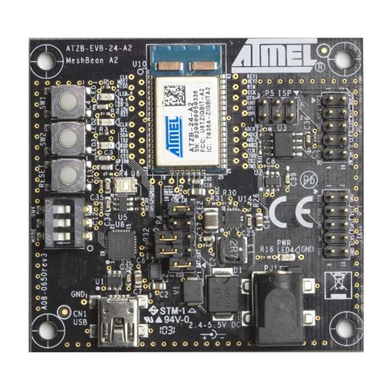
- Page 8 3.1 ATZB-EVB (MeshBean) Featured Components ZigBit Module ZigBit module is an ultra-compact, low-power, high sensitivity 2.4GHz 802.15.4/ZigBee OEM module from Atmel. ZigBit module is based on Atmel’s Z-Link 2.4GHz platform. It includes ATmega1281V Microcontroller and AT86RF230 RF Transceiver. In ZDK, every ZigBit module is delivered installed on a ATZB-EVB (MeshBean) board.
- Page 9 UID (Unique Identifier) is HEX value, 8 bytes long. UID is used for setting unique MAC address of the node. UID is hardware defined value. It is programmed into a chip (Silicon Serial Number DS2411R+ by Maxim/Dallas) at the factory. UID is unique, and cannot be overwritten.
- Page 10 Figure 1. ATZB-EVB (MeshBean) functional diagram ATZB-EVB-XXX-XXX User Manual AVR-09-2011...
-
Page 11: Connectors And Jumpers
Connectors and Jumpers The board connector pinouts and jumper settings are presented in Table 2 through Table 7. IMPORTANT NOTE: All manipulations with connectors or jumpers should be done when the board is not powered! Table 2. Expansion slot pinout Name Description UART_RTS... - Page 12 Name Description Input USART_CLK This is Clock Data Pin for USART0 interface of the ZigBit module. It is connected directly to the USART0_EXTCLK pin of the module. Digital logic level. For details, refer to ZigBit datasheet [1]. Digital/analog ground Input ADC input.
- Page 13 NOTE: JTAG connector pinout is compatible with ATmega JTAGICE mkII in- circuit emulator connector. Table 4. J1 jumper settings: current measurement Jumper Description position J1 is This position is used for normal operation. mounted In this position, the ZigBit module is not powered while J1 is open remaining parts of the board are powered.
-
Page 14: External Antenna
3.2 BitCloud Software BitCloud is a full-featured, next generation embedded software stack from Atmel. The stack provides a software development platform for reliable, scalable, and secure wireless applications running on Atmel ZigBit modules. BitCloud is designed to support a broad ecosystem of user-designed applications addressing diverse requirements and enabling a full spectrum of software customization. - Page 15 BitCloud is fully compliant with ZigBee PRO and ZigBee standards for wireless sensing and control. It provides an augmented set of APIs which, while maintaining 100% compliance with the standard, offer extended functionality designed with developer's convenience and ease-of-use in mind. The topmost of the core stack layers, APS, provides the highest level of networking- related APIs visible to the application.
-
Page 16: Getting Started
SerialNet application lets the AT-commands be interpreted locally or forwarded for execution on remote nodes; Hardware Test (see Section 4.7) is a simple application which tests major ATZB-EVB (MeshBean) board components for correct operation; Range Measurement Tool is an application intended to measure radio performance of ZigBit-based devices and/or to make comparison with platforms of other manufacturers. - Page 17 Hard disk free 50 MB space JTAG emulator JTAGICE mkII emulator Necessary to upload and debug with cable firmware onto the ATZB-EVB (MeshBean) board through JTAG (see Appendix B). Software Operating system Windows2000/XP USB driver CP210x USB to UART Necessary to connect ATZB-EVB Bridge VCP Driver (MeshBean) to PC via USB port (see Section 3.4) 4.4...
-
Page 18: Installing The Development Kit
4.3 Installing the Development Kit In order to install the Development Kit, insert the ZDK Software and Documentation CD into your PC CDROM. The ZDK installation wizard should start automatically. Specify the installation path and follow the instructions. As a result the ZDK file structure under the selected path will be generated on the PC, which is described in 10.7. - Page 19 Figure 3. COM port drivers in the Windows Device Manager window To resolve possible problems see Section 4.4. NOTE: USB to UART Bridge VCP driver for Windows platform is also available from the manufacturer’s site: http://www.silabs.com/tgwWebApp/public/web_content/products/Micro controllers/USB/en/mcu_vcp.htm. Java Runtime Environment (JRE) is also available from http://java.sun.com/javase/downloads/index.jsp.
- Page 20 Current version of the AVR Studio [16] with Service Pack can be freely downloaded from the Atmel’s website (http://www.atmel.com). Simply launch the downloaded installer programs and follow the setup instructions. The WinAVR suite of development tools can be downloaded from http://sourceforge.net/projects/winavr.
- Page 21 4.5 Powering the Boards The boards can be powered by a pair of AA-size batteries, via the USB port, once connected for data transfer, or via AC/DC adaptor. The nominal voltage is 3 V. Using AC/DC adaptor disconnects AA batteries automatically. Using USB port disconnects the AC/DC adaptor.
- Page 22 Type the “AT” command and press Enter key. The board responds to Hyper Terminal with “OK“. Now, a user can play various networking scenarios by sending AT commands fully described in [3]. A simple networking scenario for building WSN, transmitting data between the WSN nodes and accessing the nodes’...
-
Page 23: Antenna Precautions
Figure 4. Hyper Terminal Hardware Test report 4.8 Measuring Power Consumption The board allows measuring power consumption of the ZigBit module. To perform the measurements, simply connect ammeter to the clamps denoted as CM+ and CM- and remove jumper J1. Make sure that the board is powered by batteries only. However, such measurement would not be absolutely correct, because power is consumed by the interfaces and the peripherals connected to ZigBit. - Page 24 The pattern of antenna is wide. The following facts should be considered. In far-field zone, it is a horizontal plane normal to the dipoles where electromagnetic radiation appears stronger. Contrarily, at distances of several centimeters the pattern is more complex. Approximate field patterns are given in the ZigBit datasheet [1]. Handle the external antenna with care to avoid mechanical damage.
-
Page 25: Programming The Boards
WSNDemo image file can be uploaded into the boards in one of two ways: by means of Serial Bootloader utility (see Section 5.3) or in AVR Studio, using JTAG emulator. JTAGICE mkII from Atmel [17] (see Section 5.3.1) is recommended. - Page 26 5.3 Using Serial Bootloader To program a board using Serial Bootloader perform the following steps: Connect ATZB-EVB (MeshBean) to the PC via USB or serial port, depending on the position of jumper J3 (see Table ). Run Serial Bootloader. In command line, specify the image file as WSNDemo.srec (see 10.7), the COM port and the optional command line parameters.
- Page 27 Option Value EESAVE Disabled BOOTSZ Boot Flash size=1024 words start address=$FC00 BOOTRST Disabled CKDIV8 Enabled CKOUT Disabled SUT_CKSEL Int. Osc.; Start-up time: CK + 65 ms Figure 5. Fuse bits setting Make sure the following hex values appear in the bottom part of Fuses tab: 0xFF, 0x9D, 0x62.
- Page 28 If the node is to be programmed with the use of Serial Bootloader, enable additionally the BOOTRST option. Make sure the following hex value string appears at the bottom of Fuses tab: 0xFF, 0x9C, 0x62. By default, each of the boards (MCU) is preprogrammed with this fuse setting. In addition, JTAG can be used to restore the device's ability to respond to Serial Bootloader commands.
- Page 29 NOTE: While WSNDemo is running, channel mask can be changed anytime by sending the command through WSN Monitor (see Section 0). The channel mask which has been issued from WSN Monitor and received by a node is permanently stored in the node’s EEPROM, regardless of power-offs.
- Page 30 Joined to network + receiving blinking data + sending blinking data (coordinator only) Sleeping (end device only) If you power ON the coordinator, it switches to an active state, even though no child node is present. This is normal, it means that the coordinator is ready and child nodes can join the network with coordinator’s PAN ID.
- Page 31 5.6 WSN Monitor WSN Monitor is a PC-based GUI application for WSNDemo that is used to display WSN topology and other information about WSN network. See WSN Monitor screen in Figure . It contains the Topology Pane, Sensor Data Pane, Node Data Pane and Toolbars.
- Page 32 Node titles are defined in the NodeNames.txt file. By default, it is located in the following subdirectory: "./Evaluation Tools/WSNDemo (WSN Monitor)/resources/ configuration/”. Notice: the full path to the file depends on the root directory which has been specified during installation of the Development Kit (see Section 4.3). NodeNames.txt contains one “-- NodeNames --”...
- Page 33 coordinator and router and 30 sec is recommended for end device. Those timeouts cover 3 periods between packet sending. Figure 9. WSN Monitor Connection/Settings menu Node Reset A node can be reset by means of the WSN Monitor using the Tools/Send Command menu (see Figure 8).
- Page 34 The network operation is supported on 16 upper channels in 2.4 GHz band, which are numbered from 11(0x0B) through 26(0x1A). Use Tools/Send Command window to set channel mask. By default, current channel mask is displayed there (see Figure NOTE: Channel mask is a bit field which defines the channels available. The 5 most significant bits (b ) of channel mask should be ,...
- Page 35 When router is rejoining, the network indication LED, namely LED3, is blinking. Upon having router joined, LED3 is ON. When end device is rejoining, the network indication LED, LED3, is blinking. Upon having end device joined, LED3 turns ON. LED1 flashes shortly to indicate sending a packet, LED1 flashes briefly to indicate having received acknowledgement.
-
Page 36: Api Overview
Due to flexibility of AT-commands, you can create other network scenarios addressing the specific needs of your application. The examples are recommended as a starting point in evaluation of SerialNet. A variety of terminal programs provide capability to enter AT-command scripts and to analyze the responses from a board. - Page 37 MeshBean development board. 8.2 Using AVR Programming Tools It is recommended that Atmel’s AVR Studio [16] is to develop custom applications based on BitCloud API. This multiplatform Integrated Development Environment (IDE) provides the options for editing source code, compilation, linking object modules with libraries, debugging, making executable file automatically, and more.
-
Page 38: Sample Applications
file will be produced as EEPROM is not needed for Blink. To test the minimum application, upload any of the image files into a ATZB-EVB (MeshBean) board, following the instructions which are given in Section 7 or in 10.8, correspondingly. You can modify the code to extend the application’s functionality by using other BitCloud API functions. - Page 39 # Stack parameters being set to Config Server --------- CS_AUTONETWORK = 1 # If CS_AUTONETWORK is 1 CS_CHANNEL_MASK should be declared CS_CHANNEL_MASK = "(1l<<0x15)" # Parameter is used only for RF212 CS_CHANNEL_PAGE = 0 CS_RF_TX_POWER = 3 CS_END_DEVICE_SLEEP_PERIOD = 5000 CS_NEIB_TABLE_SIZE = 8 CS_MAX_CHILDREN_AMOUNT = 7 CS_MAX_CHILDREN_ROUTER_AMOUNT = 2...
-
Page 40: Troubleshooting
with AVR Studio and just execute Build/Rebuild All item from the main menu. The WSNDemoApp.hex and WSNDemoApp.srec image files will be then generated. Low-Power, Peer-to-peer and Ping-Pong applications are described in details in [4]. 9 Troubleshooting In case of any operational problem with your system please check the power first, and make sure that all of your equipment is properly connected. -
Page 41: Compliance Statement (Part 15.19)
2. These devices must accept any interference received, including interference that may cause undesired operation. 10.4 Warning (Part 15.21) Changes or modifications not expressly approved by Atmel Norway could void the user’s authority to operate the equipment. 10.5 Compliance Statement (Part 15.105(b)) This equipment has been tested and found to comply with the limits for a Class B digital device, pursuant to Part 15 of the FCC Rules. - Page 42 10.6 FCC IDs ATZB-EVB-24-A2- This equipment carries a certified Radio module with FCC ID VW4A090664 ATZB-EVB-24-SMA- This equipment carries a certified Radio module with FCC ID VW4A090665 ATZB-EVB-900-SMA- This equipment carries a certified Radio module with FCC ID VW4A090666 ...
- Page 43 ./Bootloader/GuiBootloaderSetup.msi Binary image file containing bootstrap code ./Bootloader/bootloader.hex ./Evaluation Tools/Hardware Test/ Hardware Test image files HardwareTest.srec ./Evaluation Tools/Hardware Test/ HardwareTest.hex ./Evaluation Tools/WSNDemo WSNDemo image files (Embedded)/WSNDemoApp.srec ./Evaluation Tools/WSNDemo (Embedded)/WSNDemoApp.hex WSN Monitor installer ./Evaluation Tools/WSNDemo (WSN Monitor)/WSNMonitorSetup.exe ./Evaluation Tools/SerialNet/ SerialNet image files serialnet.srec ./Evaluation Tools/SerialNet/ serialnet.hex...
- Page 44 For Windows environment it’s recommended using the AVR Studio 4.14. AVaRICE 2.40 may be used for Linux. In both cases, the recommended JTAG emulator is JTAGICE mkII from Atmel. Other programming devices can be utilized as well, but make sure before use that the particular model supports programming an Atmega1281 MCU.
- Page 45 Using AVR Studio both flash memory and EEPROM of a board can be separately programmed with images having Intel HEX format. EEPROM image has .eep extension while flash image has .hex extension. To upload firmware, follow the instructions from the device manufacturer’s manuals [16], [17], [18]. A sample pop-up window is shown in Figure .
-
Page 46: Source Code
10.9 Minimum Application Source Code /********************************************* ************** blink.c Blink application. Written by V.Marchenko ********************************************** *************/ #include "appTimer.h" #ifdef _SLIDERS_ #include "sliders.h" #endif //#ifdef _SLIDERS_ #ifdef _BUTTONS_ #include "buttons.h" #endif //#ifdef _BUTTONS_ #ifdef _LEDS_ #include "leds.h" #endif //#ifdef _LEDS_ #include "zdo.h" #ifndef BLINK_PERIOD #define BLINK_PERIOD 1000 // Initial blink period, ms. - Page 47 #define BLINK_INTERVAL (BLINK_PERIOD / 2) // Blink interval. #define MIN_BLINK_INTERVAL (MIN_BLINK_PERIOD / 2) // Minimum blink interval. #define MAX_BLINK_INTERVAL (MAX_BLINK_PERIOD / 2) // Maximum blink interval. #ifndef _BUTTONS_ #define BSP_KEY0 #define BSP_KEY1 #endif //#ifndef _BUTTONS_ #define HALF_PERIOD_BUTTON BSP_KEY0 // Button that reduces blink interval to a half.
- Page 48 ********************************************** *************/ void APL_TaskHandler(void) #ifdef _LEDS_ BSP_OpenLeds(); // Enable LEDs #endif //#ifdef _LEDS_ #ifdef _BUTTONS_ BSP_OpenButtons(NULL, buttonsReleased); // Register button event handlers #else // Configure blink timer changeBlinkTimer.interval = 10000; // Timer interval changeBlinkTimer.mode TIMER_REPEAT_MODE; // Repeating mode (TIMER_REPEAT_MODE or TIMER_ONE_SHOT_MODE) changeBlinkTimer.callback = changeTimerFired;...
- Page 49 button = HALF_PERIOD_BUTTON; #endif //#ifndef _BUTTONS_ /********************************************* ************** Description: blinking timer fire event handler. Parameters: none. Returns: nothing. ********************************************** *************/ static void blinkTimerFired() BSP_ToggleLed(LED_RED); BSP_ToggleLed(LED_YELLOW); BSP_ToggleLed(LED_GREEN); /********************************************* ************** Description: button release event handler. Parameters: buttonNumber - released button number. Returns: nothing. ********************************************** *************/ static void buttonsReleased(uint8_t...
- Page 50 else if (DOUBLE_PERIOD_BUTTON == buttonNumber) blinkTimer.interval *= 2; if (blinkTimer.interval > MAX_BLINK_INTERVAL) blinkTimer.interval = MAX_BLINK_INTERVAL; blinkTimerFired(); // Update LED status immediately. HAL_StartAppTimer(&blinkTimer); // Start updated blink timer. /********************************************* ************** Description: just a stub. Parameters: are not used. Returns: nothing. ********************************************** *************/ void ZDO_MgmtNwkUpdateNotf(ZDO_MgmtNwkUpdateNotf_t...
- Page 51 /********************************************* ************** Description: just a stub. Parameters: none. Returns: nothing. ********************************************** *************/ void ZDO_SleepInd(void) //eof blink.c Makefile # Components path definition ----------------- --------- COMPONENTS_PATH = ../../Components # Application makerules including ------------ --------- include $(COMPONENTS_PATH)/../lib/MakerulesBcAll # Project name ------------------------------- --------- PRJ_NAME = blink # Application parameters --------------------- --------- CFLAGS += -DBLINK_PERIOD=1000...
- Page 52 # Stack libraries paths ---------------------- -------- LIB_PATH = -L$(COMPONENTS_PATH)/../lib \ -L$(PDS_PATH)/lib -L$(CS_PATH)/lib -L$(BSP_PATH)/lib ## Stack include paths ----------------------- --------- INCLUDES = -I$(SE_PATH)/include -I$(APS_PATH)/include -I$(NWK_PATH)/include -I$(ZDO_PATH)/include -I$(MAC_PHY_PATH)/include \ -I$(HAL_PATH)/include -I$(HAL_HWD_PATH)/include \ -I$(BSP_PATH)/include -I$(CS_PATH)/include -I$(PDS_PATH)/include -I$(TC_PATH)/include -I$(SSP_PATH)/include # Linking ------------------------------------ --------- ifeq ($(HAL), ATMEGA1281) LINK_OBJECTS = $(COMPONENTS_PATH)/../lib/WdtInitatmega1281.o LINKER_FLAGS = -o$(PRJ_NAME).elf -...
- Page 53 all: pds cs $(PRJ_NAME).elf $(PRJ_NAME).srec $(PRJ_NAME).hex $(PRJ_NAME).bin \ size pds: @echo @echo -------PDS library creation----------- ------------- make all -C $(PDS_PATH) @echo @echo -------Configuration Server library creation------- make all -C $(CS_PATH) $(PRJ_NAME).o: %.o: %.c @echo @echo -------Application executable creation------------- $(CC) -c $(CFLAGS) $(INCLUDES) $^ -o $@ $(PRJ_NAME).elf: $(PRJ_NAME).o $(CC) $(CFLAGS) $(INCLUDES)
- Page 54 # Cleaning... -------------------------------- ---------- clean: @echo @echo -------Application cleaning----------- ------------- rm -rf $(PRJ_NAME).elf $(PRJ_NAME).hex $(PRJ_NAME).srec $(PRJ_NAME).o $(PRJ_NAME).map $(PRJ_NAME).bin @echo @echo -------PDS library cleaning----------- ------------- make clean -C $(PDS_PATH) @echo @echo -------Configuration Server library cleaning------- make clean -C $(CS_PATH) @echo # eof Makefile ATZB-EVB-XXX-XXX User Manual AVR-09-2011...
-
Page 55: Evaluation Board/Kit Important Notice
(WEEE), FCC, CE or UL (except as may be otherwise noted on the board/kit). Atmel supplied this board/kit “AS IS,” without any warranties, with all faults, at the buyer’s and further users’ sole risk. - Page 56 BEEN ADVISED OF THE POSSIBILITY OF SUCH DAMAGES. Atmel makes no representations or warranties with respect to the accuracy or completeness of the contents of this document and reserves the right to make changes to specifications and product descriptions at any time without notice. Atmel does not make any commitment to update the information contained herein.
Need help?
Do you have a question about the ATZB-EVB-24-SMA and is the answer not in the manual?
Questions and answers