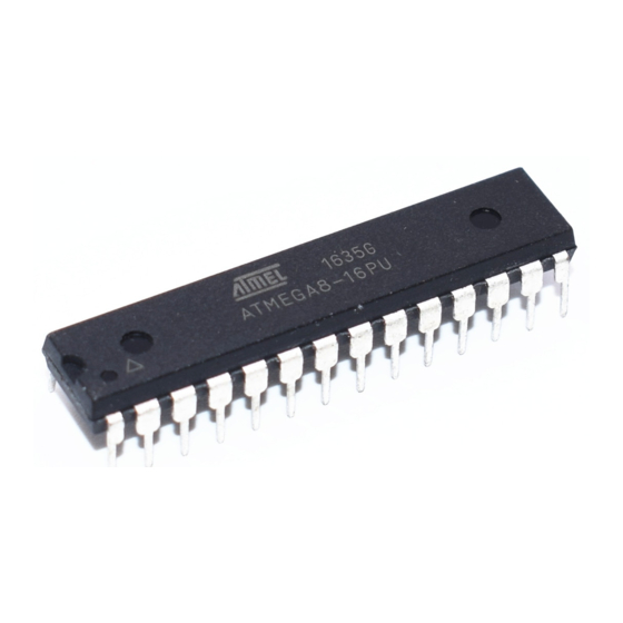
Table of Contents
Advertisement
Features
•
High-performance, Low-power Atmel
•
Advanced RISC Architecture
– 130 Powerful Instructions – Most Single-clock Cycle Execution
– 32 × 8 General Purpose Working Registers
– Fully Static Operation
– Up to 16MIPS Throughput at 16MHz
– On-chip 2-cycle Multiplier
•
High Endurance Non-volatile Memory segments
– 8Kbytes of In-System Self-programmable Flash program memory
– 512Bytes EEPROM
– 1Kbyte Internal SRAM
– Write/Erase Cycles: 10,000 Flash/100,000 EEPROM
– Data retention: 20 years at 85°C/100 years at 25°C
– Optional Boot Code Section with Independent Lock Bits
In-System Programming by On-chip Boot Program
True Read-While-Write Operation
– Programming Lock for Software Security
•
Peripheral Features
– Two 8-bit Timer/Counters with Separate Prescaler, one Compare Mode
– One 16-bit Timer/Counter with Separate Prescaler, Compare Mode, and Capture
Mode
– Real Time Counter with Separate Oscillator
– Three PWM Channels
– 8-channel ADC in TQFP and QFN/MLF package
Eight Channels 10-bit Accuracy
– 6-channel ADC in PDIP package
Six Channels 10-bit Accuracy
– Byte-oriented Two-wire Serial Interface
– Programmable Serial USART
– Master/Slave SPI Serial Interface
– Programmable Watchdog Timer with Separate On-chip Oscillator
– On-chip Analog Comparator
•
Special Microcontroller Features
– Power-on Reset and Programmable Brown-out Detection
– Internal Calibrated RC Oscillator
– External and Internal Interrupt Sources
– Five Sleep Modes: Idle, ADC Noise Reduction, Power-save, Power-down, and
Standby
•
I/O and Packages
– 23 Programmable I/O Lines
– 28-lead PDIP, 32-lead TQFP, and 32-pad QFN/MLF
•
Operating Voltages
– 2.7V - 5.5V (ATmega8L)
– 4.5V - 5.5V (ATmega8)
•
Speed Grades
– 0 - 8MHz (ATmega8L)
– 0 - 16MHz (ATmega8)
•
Power Consumption at 4Mhz, 3V, 25C
– Active: 3.6mA
– Idle Mode: 1.0mA
– Power-down Mode: 0.5µA
®
®
AVR
8-bit Microcontroller
(1)
8-bit Atmel with
8KBytes In-
System
Programmable
Flash
ATmega8
ATmega8L
Summary
Rev.2486AAS–AVR–02/2013
Advertisement
Table of Contents

Summary of Contents for Atmel ATmega8
- Page 1 – 23 Programmable I/O Lines – 28-lead PDIP, 32-lead TQFP, and 32-pad QFN/MLF • Operating Voltages – 2.7V - 5.5V (ATmega8L) – 4.5V - 5.5V (ATmega8) • Speed Grades – 0 - 8MHz (ATmega8L) – 0 - 16MHz (ATmega8) •...
-
Page 2: Pin Configurations
ATmega8(L) PDIP Configurations (RESET) PC6 PC5 (ADC5/SCL) (RXD) PD0 PC4 (ADC4/SDA) (TXD) PD1 PC3 (ADC3) (INT0) PD2 PC2 (ADC2) (INT1) PD3 PC1 (ADC1) (XCK/T0) PD4 PC0 (ADC0) AREF (XTAL1/TOSC1) PB6 AVCC (XTAL2/TOSC2) PB7 PB5 (SCK) (T1) PD5 PB4 (MISO) (AIN0) PD6... -
Page 3: Block Diagram
The Atmel ATmega8 is a low-power CMOS 8-bit microcontroller based on the AVR RISC architecture. By executing powerful instructions in a single clock cycle, the ATmega8 achieves throughputs approaching 1MIPS per MHz, allowing the system designer to optimize power con- sumption versus processing speed. - Page 4 ATmega8 is a powerful microcontroller that provides a highly-flexible and cost-effective solution to many embedded control applications. The ATmega8 is supported with a full suite of program and system development tools, including C compilers, macro assemblers, program simulators, and evaluation kits.
-
Page 5: Pin Descriptions
The Port D pins are tri-stated when a reset condition becomes active, even if the clock is not running. Port D also serves the functions of various special features of the ATmega8 as listed on page RESET Reset input. -
Page 6: Ordering Information
32M1-A Notes: 1. This device can also be supplied in wafer form. Please contact your local Atmel sales office for detailed ordering information and minimum quantities 2. Pb-free packaging complies to the European Directive for Restriction of Hazardous Substances (RoHS directive). Also Halide free and fully Green 3. -
Page 7: Packaging Information
ATmega8(L) Packaging Information PIN 1 IDENTIFIER PIN 1 0°~7° COMMON DIMENSIONS (Unit of measure = mm) SYMBOL NOTE – – 1.20 0.05 – 0.15 0.95 1.00 1.05 8.75 9.00 9.25 6.90 7.00 7.10 Note 2 8.75 9.00 9.25 Notes: 6.90 7.00... - Page 8 ATmega8(L) 28P3 SEATING PLANE (4 PLACES) COMMON DIMENSIONS (Unit of Measure = mm) 0º ~ 15º SYMBOL NOTE – – 4.5724 0.508 – – 34.544 – 34.798 Note 1 7.620 – 8.255 7.112 – 7.493 Note 1 0.381 – 0.533 1.143...
-
Page 9: Side View
ATmega8(L) 32M1-A Pin 1 ID SIDE VIEW TOP VIEW COMMON DIMENSIONS 0.08 C (Unit of Measure = mm) SYMBOL NOTE 0.80 0.90 1.00 – 0.02 0.05 – 0.65 1.00 Pin #1 Notch (0.20 R) 0.20 REF 0.18 0.23 0.30 4.90 5.00... - Page 10 Use external capacitors in the range of 20pF - 36pF on XTAL1/TOSC1 and XTAL2/TOSC2. This will be fixed in ATmega8 Rev. G where the CKOPT Fuse will control internal capacitors also when internal RC Oscillator is selected as main clock source. For ATmega8 Rev. G, CKOPT = 0 (programmed) will enable the internal capacitors on XTAL1 and XTAL2.
- Page 11 ATmega8(L) 5. Reading EEPROM by using ST or STS to set EERE bit triggers unexpected interrupt request. Reading EEPROM by using the ST or STS command to set the EERE bit in the EECR reg- ister triggers an unexpected EEPROM interrupt request.
- Page 12 Other terms and product names may be trademarks of others. Disclaimer: The information in this document is provided in connection with Atmel products. No license, express or implied, by estoppel or otherwise, to any intellectual property right is granted by this document or in connection with the sale of Atmel products.


Need help?
Do you have a question about the ATmega8 and is the answer not in the manual?
Questions and answers