Table of Contents
Advertisement
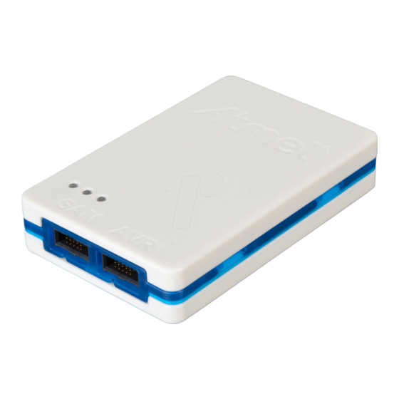
The Atmel-ICE Debugger
Atmel-ICE is a powerful development tool for debugging and programming
®
®
ARM
Cortex
-M based Atmel
Chip Debug capability.
It supports:
●
Programming and on-chip debugging of all Atmel AVR 32-bit
microcontrollers on both JTAG and aWire interfaces
●
Programming and on-chip debugging of all Atmel AVR XMEGA
devices on both JTAG and PDI 2-wire interfaces
●
Programming (JTAG and SPI) and debugging of all Atmel AVR 8-bit
microcontrollers with OCD support on either JTAG or debugWIRE interfaces
●
Programming and debugging of all Atmel SAM ARM Cortex-M based
microcontrollers on both SWD and JTAG interfaces
●
Programming (TPI) of all Atmel tinyAVR
for this interface
Consult the supported devices list in the Atmel Studio User Guide for a full list of
devices and interfaces supported by this firmware release.
®
®
SAM and Atmel AVR
microcontrollers with On-
®
8-bit microcontrollers with support
USER GUIDE
Atmel-ICE
®
family
42330A-MCU-07/2014
Advertisement
Table of Contents

Related Manuals for Atmel Atmel-ICE


Summary of Contents for Atmel Atmel-ICE
-
Page 1: The Atmel-Ice Debugger
● ® Programming (TPI) of all Atmel tinyAVR 8-bit microcontrollers with support for this interface Consult the supported devices list in the Atmel Studio User Guide for a full list of devices and interfaces supported by this firmware release. 42330A-MCU-07/2014... -
Page 2: Table Of Contents
Atmel OCD Implementations ..........23 4.3.1. Atmel AVR UC3 OCD (JTAG and aWire) ...... 23 4.3.2. Atmel AVR XMEGA OCD (JTAG and PDI Physical) ..24 4.3.3. Atmel megaAVR OCD (JTAG) ........24 4.3.4. Atmel megaAVR / tinyAVR OCD (debugWIRE) ....24 4.3.5. - Page 3 11.2. Firmware Release History ............. 38 11.2.1. Atmel Studio 6.2 ............. 38 11.2.2. Atmel Studio 6.2 (beta)2 ........... 38 11.3. Known Issues Concerning the Atmel-ICE ......... 38 11.3.1. Atmel AVR XMEGA OCD Specific Issues ..... 38 11.3.2. Atmel megaAVR OCD and Atmel tinyAVR OCD Specific Issues ............
-
Page 4: Introduction
6-pin 50-mil, 10-pin 100-mil and 20-pin 100-mil headers. Several kit options are available with different cabling and adapters. System Requirements The Atmel-ICE unit requires that a front-end debugging environment Atmel Studio version 6.2 or later is installed on your computer. Atmel-ICE [USER GUIDE]... - Page 5 The Atmel-ICE should be connected to the host computer using the USB cable provided, or a certified USB- micro cable. Atmel-ICE [USER GUIDE] 42330A-MCU-07/2014...
-
Page 6: Getting Started With The Atmel-Ice
Getting Started with the Atmel-ICE Full Kit Contents The Atmel-ICE full kit contains these items: ● Atmel-ICE unit ● USB cable (1.8m, high-speed, micro-B) ● Adapter board containing 50-mil AVR, 100-mil AVR/SAM and 100-mil 20-pin SAM adapters ● IDC flat cable with 10-pin 50-mil connector and 6-pin 100-mil connector ●... -
Page 7: Pcba Kit Contents
Figure 2-2. Atmel-ICE Basic Kit Contents PCBA Kit Contents The Atmel-ICE PCBA kit contains these items: ● Atmel-ICE unit without plastic encaptulation Figure 2-3. Atmel-ICE PCBA Kit Contents Spare Parts Kits The following spare parts kits are available: ● Adapter kit ●... -
Page 8: Kit Overview
PCBA cable kit Assembling the Atmel-ICE The Atmel-ICE unit is shipped with no cables attached. Two cable options are provided in the full kit: ● 50-mil 10-pin IDC flat cable with 6-pin ISP and 10-pin connectors Atmel-ICE [USER GUIDE]... - Page 9 To assemble your Atmel-ICE into its default configuration, connect the 10-pin 50-mil IDC cable to the unit as shown below. Be sure to orient the cable so that the red wire (pin 1) on the cable aligns with the triangular indicator on the blue belt of the enclosure.
-
Page 10: Opening The Atmel-Ice
Opening the Atmel-ICE Note For normal operation, the Atmel-ICE unit must not be opened. Opening the unit is done at your own risk. Anti-static precautions should be taken. The Atmel-ICE enclosure consists of three separate plastic components - top cover, bottom cover and blue belt - which are snapped together during assembly. - Page 11 Figure 2-12. Opening the Atmel-ICE (1) Figure 2-13. Opening the Atmel-ICE (2) Atmel-ICE [USER GUIDE] 42330A-MCU-07/2014...
-
Page 12: Powering The Atmel-Ice
Powering the Atmel-ICE The Atmel-ICE is powered by the USB bus voltage. It requires less than 100mA to operate, and can therefore be powered through a USB hub. The power LED will illuminate when the unit is plugged in. When not connected in an active programming or debugging session, the unit will enter low-power consumption mode to preserve your computer's battery. -
Page 13: Connecting The Atmel-Ice
Use the 50-mil 10-pin flat cable (included in some kits) to connect directly to a board supporting this header type. Use the AVR connector port on the Atmel-ICE for headers layed out in the AVR pinout, and the SAM connector port for headers complying with the ARM Cortex Debug header pinout. -
Page 14: Connecting To An Awire Target
Use the adapter board (included in some kits) to connect to a standard 50-mil aWire header. Connection to a custom 100-mil header The 10-pin mini-squid cable should be used to connect between the Atmel-ICE AVR connector port and the target board. Three connections are required, as described in the table below. -
Page 15: Connecting To A Pdi Target
Use the adapter board (included in some kits) to connect to a standard 50-mil PDI header. Connection to a custom 100-mil header The 10-pin mini-squid cable should be used to connect between the Atmel-ICE AVR connector port and the target board. Four connections are required, as described in the table below. -
Page 16: Connecting To A Spi Target
RESET pin. The debugWIRE OCD is capable of disabling itself temporarily (using the button on the debugging tab in the properties dialog in Atmel Studio), thus releasing control of the RESET line. The SPI interface is then available again (only if the SPIEN fuse is programmed), allowing the DWEN fuse to be un-programmed using the SPI interface. -
Page 17: Connecting To A Tpi Target
Use the adapter board (included in some kits) to connect to a standard 50-mil TPI header. Connection to a custom 100-mil header The 10-pin mini-squid cable should be used to connect between the Atmel-ICE AVR connector port and the target board. Six connections are required, as described in Table 3-6, “Atmel-ICE TPI Pin... - Page 18 When using STK600 or a board making use of the AVR JTAG pinout, the AVR connector port on the Atmel-ICE must be used. When connecting to a board which makes use of the ARM JTAG pinout, the SAM connector port on the Atmel-ICE must be used.
-
Page 19: On-Chip Debugging
– something not technically realisable with a traditional emulator. Run Mode When in Run mode, the execution of code is completely independent of the Atmel-ICE. The Atmel-ICE will continuously monitor the target device to see if a break condition has occurred. When this happens the OCD system will interrogate the device through its debug interface, allowing the user to view the internal state of the device. - Page 20 Reset (optional) Used to reset the target device. Connecting this pin is recommended since it allows the Atmel-ICE to hold the target device in a reset state, which can be essential to debugging in certain scenarios. Target voltage reference. The Atmel-ICE samples the target voltage on this pin in order to power the level converters correctly.
-
Page 21: Awire
TMS and TCK are connected in parallel; TDI and TDO are connected in a serial chain ● nSRST on the Atmel-ICE probe must be connected to RESET on the devices if any one of the devices in the chain disables its JTAG port ●... -
Page 22: Pdi Physical
PDI Physical is a 2-pin interface providing a bi-directional half-duplex synchronous communication with the target device. When designing an application PCB which includes an Atmel AVR with the PDI interface, the pinout shown in Figure 4-6, “PDI Header Pinout” on page 22 should be used. -
Page 23: Tpi
The Atmel-ICE is capable of streaming UART-format ITM trace to the host computer. Trace is captured on the TRACE/SWO pin of the 10-pin header (JTAG TDO pin). Data is buffered internally on the Atmel-ICE and is sent over the HID interface to the host computer. The maximum reliable data rate is about 3MB/s. -
Page 24: Atmel Avr Xmega Ocd (Jtag And Pdi Physical)
“Atmel megaAVR OCD (JTAG)” on page 4.3.4 Atmel megaAVR / tinyAVR OCD (debugWIRE) The debugWIRE OCD is a specialised OCD module with a limited feature set specially designed for Atmel AVR devices with low pin-count. It supports the following features: ●... -
Page 25: Hardware Description
The rear panel of the Atmel-ICE houses the micro-B USB connector. Bottom Panel The bottom panel of the Atmel-ICE has a sticker which shows the serial number and date of manufacture. When seeking technical support, include these details. Atmel-ICE [USER GUIDE]... -
Page 26: Architecture Description
Atmel-ICE Mainboard Power is supplied to the Atmel-ICE from the USB bus, regulated to 3.3V by a step-down switchmode regulator. The VTG pin is used as a reference input only, and a separate power supply feeds the variable-voltage side of the on-board level converters At the heart of the Atmel-ICE mainboard is the Atmel AVR UC3 microcontroller AT32UC3A4256, which runs at between 1MHz and 60MHz depending on the tasks being processed. -
Page 27: Atmel-Ice Target Connectors
Atmel-ICE Target Connectors The Atmel-ICE does not have an active probe. A 50-mil IDC cable is used to connect to the target application either directly, or through the adapters included in some kits. For more information on the cabling and adapters,... -
Page 28: Software Integration
AVR UC3 programming on aWire interface is clocked by the programmer. The optimal frequency is given by the SAB bus speed in the target device. The Atmel-ICE debugger will automatically tune the aWire baud rate to meet this criteria. Although it's usually not necessary the user can limit the maximum baud rate if needed (e.g. - Page 29 Debug sessions on UC3 target devices over the aWire interface will be automatically tuned to the optimal baud rate by the Atmel-ICE itself. However, if you are experiencing reliability problems related to a noisy debug environment, it is possible to force the aWire speed below a configurable limit.
-
Page 30: Command Line Utility
Atmel Atmel-ICE. During the Atmel Studio installation a shortcut called Atmel Studio 6.2 Command Prompt were created in the Atmel folder on the Start menu. By double clicking this shortcut a command prompt will be opened and programming commands can be entered. The command line utility is installed in the Atmel Studio installation path in the folder Atmel/Atmel Studio 6.2/atbackend/. -
Page 31: Advanced Debugging Techniques
Atmel AVR UC3 Targets 8.1.1 EVTI / EVTO Usage The EVTI and EVTO pins are not accessible on the Atmel-ICE. However, they can still be used in conjunction with other external equipment. EVTI can be used for the following purposes: ●... -
Page 32: Special Considerations
● One data breakpoint with address range, value range or both Atmel Studio will tell you if the breakpoint can't be set, and why. Data breakpoints have priority over program breakpoints, if software breakpoints are available. External reset and PDI physical The PDI physical interface uses the reset line as clock. -
Page 33: Atmel Megaavr Ocd (Jtag)
Accessing 16-bit Registers The Atmel AVR peripherals typically contain several 16-bit registers that can be accessed via the 8-bit data bus (eg: TCNTn of a 16-bit timer). The 16-bit register must be byte accessed using two read or write operations. -
Page 34: Debugwire Ocd
When the application program writes a byte of data to the OCDR register of the AVR device being debugged, the Atmel-ICE reads this value out and displays it in the message window of the software front-end. The IDR register is polled every 50ms, so writing to it at a higher frequency will NOT yield reliable results. When the AVR device loses power while it is being debugged, spurious IDR events may be reported. -
Page 35: Atmel Avr Uc3 Ocd
Some SAM devices include an ERASE pin which is asserted to perform a complete chip erase and unlock devices on which the security bit is set. This pin is NOT routed to any debug header, and thus the Atmel-ICE is unable to unlock a device. - Page 36 SWD interface The RESET line should always be connected so that the Atmel-ICE can enable the SWD interface. Atmel-ICE [USER GUIDE] 42330A-MCU-07/2014...
-
Page 37: Firmware Upgrade
Firmware Upgrade For information on how to upgrade the firmware, see the Atmel Studio user guide in Atmel Studio (USER GUIDE). Atmel-ICE [USER GUIDE] 42330A-MCU-07/2014... -
Page 38: Release History And Known Issues
Cycling power on ATmega32U6 during a debug session may cause a loss of contact with the device 11.4 Device Support For a full device support table for all Atmel Tools, see the “Supported Devices” in Atmel Studio (USER GUIDE). Atmel-ICE [USER GUIDE]... -
Page 39: Product Compliance
Product Compliance 12.1 RoHS and WEEE The Atmel-ICE (all kits) and its accessories are manufactured in accordance to both the RoHS Directive (2002/95/EC) and the WEEE Directive (2002/96/EC). 12.2 CE and FCC The Atmel-ICE unit has been tested in accordance to the essential requirements and other relevant provisions of Directives: ●... -
Page 40: Document Revisions
Document Revisions Document Date Comment revision 42330A 06/2014 Initial document for release. Atmel-ICE [USER GUIDE] 42330A-MCU-07/2014... - Page 41 OR LOSS OF INFORMATION) ARISING OUT OF THE USE OR INABILITY TO USE THIS DOCUMENT, EVEN IF ATMEL HAS BEEN ADVISED OF THE POSSIBILITY OF SUCH DAMAGES. Atmel makes no representations or warranties with respect to the accuracy or completeness of the contents of this document and reserves the right to make changes to specifications and products descriptions at any time without notice.
Need help?
Do you have a question about the Atmel-ICE and is the answer not in the manual?
Questions and answers