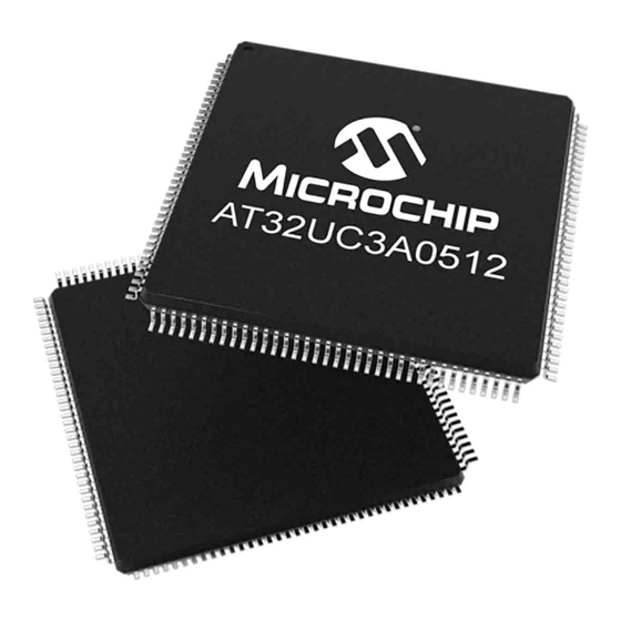
Atmel AT32UC3 Series Application Note

Atmel AT32UC3 Series Application Note

Space vector modulation using avr32 uc3 microcontroller

Advertisement

AVR32710: Space Vector Modulation using AVR32 UC3
Features
Brushless DC Motor
Space Vector Pulse Width Modulation using 6 PWM channels
Source Code for GCC compiler
®
Use AVR
32 Digital Signal Processing library (DSPLib)
1. Introduction
This application note outlines a demonstration using a stand-alone application on an
AVR32 target. It is a real-time system that computes Space Vector Modulation on a
Brushless DC Motor.
The Space Vector Modulation technique is described in application note AVR435
available on www.atmel.com.
This application is designed to work with the EVK1100 evaluation kit, therefore all the
following information is specific to this board and this specific microcontroller
(AVR32UC3A). Additionally, this application can be easily used by the EVK1101 eval-
uation kit and the specific microcontroller (AVR32UC3B).
Microcontroller
Figure 1-1.
Block Diagram
AVR32UC3
DSP
6 PWMs
Library
channels
Scheduler
3 GPIO
inputs
LCD Display
BLDC
Motor
U
V
Vn
W
Hall Sensors
HallA
HallB
HallC
32-bit
Microcontroller
Application Note
Rev. 32094B-AVR32-05/09

Advertisement

Table of Contents
loading
Need help?

Need help?

Do you have a question about the AT32UC3 Series and is the answer not in the manual?

Questions and answers

Subscribe to Our Youtube Channel

Summary of Contents for Atmel AT32UC3 Series

  • Page 1 Brushless DC Motor. The Space Vector Modulation technique is described in application note AVR435 available on www.atmel.com. This application is designed to work with the EVK1100 evaluation kit, therefore all the following information is specific to this board and this specific microcontroller (AVR32UC3A).
  • Page 2: Related Parts

    • ® – IAR Embedded Workbench for Atmel AVR32: IAR Embedded Workbench provides a suite of AVR32 development tools for embedded systems (compiler, assembler, linker, debugger). http://www.iar.com/ • EVK1100: The EVK1100 is an evaluation kit and development system for the AVR32 AT32UC3A microcontroller.
  • Page 3 AVR32710 4. Abbreviations • BLDC: Brushless Direct Current • SVPWM : Space Vector Pulse Width Modulation • CW : Clockwise direction / CCW : Counter Clockwise direction • FCPU : CPU frequency • FPBA : Peripheral Bus A frequency 32094B–AVR32–05/09...
  • Page 4 5. Motor Control Theory Introduction The most common method used to control DC motors is to modulate the voltage and especially the duty cycle. This is called the Space Vector Pulse Width Modulation (S.V.P.W.M). At first, this application note describes the S.V.P.W.M technique and then how to implement BLDC motor control algorithm on AVR32 UC3 devices.
  • Page 5 AVR32710 Figure 5-2. Possible switching configurations of a 3-phase inverter Possible Switching Configuration of a 3-phase inverter These combinations generates eight 3-phases voltages combination Table 5-1. Switching configurations and output voltages of a 3-phase inverter -Vdc/3 -Vdc/3 +2Vdc/3 -Vdc/3 +2Vdc/3 -Vdc/3 -2Vdc/3 -Vdc/3...
  • Page 6 5.2.2 New Space Vectors using Clarke Transformation Figure 5-3. Basic Space Vectors θ θ These 3-phases voltage combinations are converted by Clarke transformation and could be expressed in complex form. In sector (1), for example, Π Π ⎡ ⎤ ⎡ ⎤...
  • Page 7 AVR32710 It implies as well that switching configuration tables could be expressed in (d-q) format Table 5-2. Switching configurations and output voltages of a 3-phase in (d-q) format Vector Sector 2Vdc/3 +Vdc/3 +Vdc/3 -Vdc/3 +Vdc/3 -2Vdc/3 -Vdc/3 -Vdc/3 Vdc/3 -Vdc/3 Each space vector corresponding to WH,VH and UH could be expressed as a combination of Vds and Vqs (vector list in Figure...
  • Page 8 6. Motor Control Processing computations Flow Chart Diagram From the SVPWM technique, it is possible to distinguish several actions: • Sector Determination • PI Corrector • Space Vector Computation Before starting application development, it could be interesting to consider clock source reference: •...
  • Page 9 AVR32710 Space Vector Modulation For an efficient implementation of SV-PWM, we use DSP library for cosinus and sinus computation. Π θ − sin( θ sin( Once dx and dy are calulated, a set of 3 compare values Ta,Tb and Tc need to be calculated every PWM period to generate this pattern.
  • Page 10 We can say that for this sector 0: − − − PWM duty cycle results with SVPWM computation Table 6-1. Sector Number direction = CCW direction = CW PWM0 = (T - dx -dy)/2 PWM0 = (T + dx + dy) 0 π...
  • Page 11 AVR32710 6.2.1 Pulse Width Modulation Generation 6.2.1.1 Using PWM module The AVR32 UC3 is able to generate PWM signals through a dedicated PWM module or through the Timer Counter used. The PWM module is used in this application • We need first to setup alternate functions of GPIO corresponding to alternate pins/functions used for PWM channels.
  • Page 12 Tick Reference Generation The tick reference is generated with a timer counter usage. The AVR32 UC3 family is able to generate timer event signals through a dedicated Timer Coun- ter module or through CPU cycle counter mode. Only the Timer Counter is used in this application Timer Counter module could be used in Capture Mode or Waveforme Mode.
  • Page 13 AVR32710 Hall Estimator Each Hall sensor is connected to GPIO. All GPIOs are able to generate interrupts. By default, interrupts are configured to be used with pin level changes. 6.4.1 Sector determination The Sector Determination is based on the reading of the three Hall sensors. During one electri- cal revolution, the three Hall sensors generate 6 steps.
  • Page 14: Software Implementation

    7. Software Implementation Figure 7-1. Block diagram PERIOD_REGULATION_TASK task #1 amplitude UH(Q1) SVPWM Hall A UL(Q2) HALL_ESTIMATOR computation YH(Q3) GPIO task #2 task #2 Hall B YL(Q4) (Section 5.4) (Section 5.2) ZH(Q5) ZL(Q6) Hall C Prescalor tick period_regulation Timer Counter (Section 5.3) Environment Layer HARDWARE Layer...
  • Page 15 AVR32710 Source Code Package Description The software is available in the attached project on the Atmel web Site. The AVR32710.zip con- tains the project for the UC3A0512 Rev. E (engineering samples). The EVK110x-MOTOR- CONTROL-X.Y.Z.ES supports the UC3A0512 Rev. E only.
  • Page 16: Hardware Implementation

    8. Hardware Implementation EVK1100 Connection The Table 8-1 lists the connections between evaluation kit and motor connection. Table 8-1. EVK1100 and Power Bridge Connection Power Bridg EVK1100 PWM0 PWM1 PWM2 PWM3 PWM4 PWM5 GPIO/10 GPIO/29 GPIO/30 Power Bridge Presentation The power bridge board is made up of standard complementary MOSFETs IRF3504.A adapta- tion stage is used to convert digital signals into analog signals to correctly adress MOSFETs.
  • Page 17: Running The Application

    Loading the Code The AVR32 UC3 ISP solution offers an easy way to download files into AVR32 products on Atmel Evaluation Kits through the JTAG link (via the JTAGICE mkII debugger tools) or the USB bootloader. Follow the steps below to build the application, load and run the code: If you are using GCC with the AVR32 GNU Toolchain : - Make sure the board is powered off.
  • Page 18 Running the Application • Power up the board. The LCD displays : – State of the motor (Run or Stop) – Speed Motor value (In percent of maximum value) – Direction (Forward or Backward) • Push Up the Joystick. The motor starts to run •...
  • Page 19 Disclaimer: The information in this document is provided in connection with Atmel products. No license, express or implied, by estoppel or otherwise, to any intellectual property right is granted by this document or in connection with the sale of Atmel products. EXCEPT AS SET FORTH IN ATMEL’S TERMS AND CONDI- TIONS OF SALE LOCATED ON ATMEL’S WEB SITE, ATMEL ASSUMES NO LIABILITY WHATSOEVER AND DISCLAIMS ANY EXPRESS, IMPLIED OR STATUTORY...

Table of Contents