Advertisement
Quick Links
EPILOG LASER
16371 Table Mountain Parkway
Golden, Colorado 80403
Phone 303-215-9171
FAX 303-277-9669
www.epiloglaser.com
Fan Assembly Upgrade
Requirements:
Tools:
•
Phillips Head Screwdriver
•
Flathead Screwdriver
•
3/16" Nut Driver or Socket Wrench
•
Wire Snips
:
Parts
•
MT314 – Motor Fan Kit Upgrade
•
(or) MT315 – Motor Fan Kit Upgrade w/ AS07000ATT-03-M-02 X Motor
Overview:
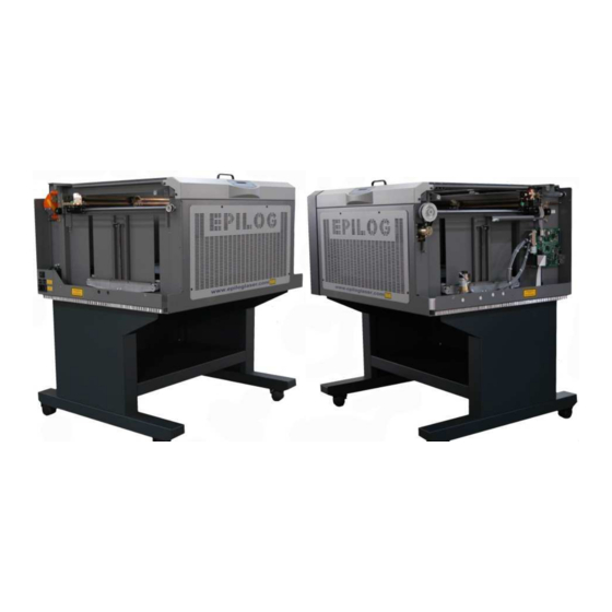
This procedure will cover installing the fan assembly for the X axis motor.
Fan Assembly Upgrade
Mini / Helix
Revision Date: 2/21/2013
For the Epilog Mini / Helix
2/21/2013
pg. 1 of 11
Advertisement

Summary of Contents for Epilog Laser Mini
- Page 1 EPILOG LASER 16371 Table Mountain Parkway Golden, Colorado 80403 Phone 303-215-9171 FAX 303-277-9669 www.epiloglaser.com Fan Assembly Upgrade For the Epilog Mini / Helix 2/21/2013 Requirements: Tools: • Phillips Head Screwdriver • Flathead Screwdriver • 3/16” Nut Driver or Socket Wrench •...
- Page 2 4. While holding the pulley to the right hand side of the engraver, tighten the screw towards the rear of Step 4-C & 4-D the engraver. This will hold the pulley in place. Fan Assembly Upgrade Mini / Helix Revision Date: 2/21/2013 pg. 2 of 11...
- Page 3 Step 7 Remove the motor by pulling it straight up. You may need to angle the motor slightly so that the belt falls from the drive pulley. Fan Assembly Upgrade Mini / Helix Revision Date: 2/21/2013 pg. 3 of 11...
- Page 4 Fan Assembly Upgrade Mini / Helix Revision Date: 2/21/2013 pg. 4 of 11...
- Page 5 Disconnect the X axis ribbon cable from the X/Y Interface PCB. Step 3 Remove the screws on the top of the Cover Plate, remove and discard the cover plate. Fan Assembly Upgrade Mini / Helix Revision Date: 2/21/2013 pg. 5 of 11...
- Page 6 Step 4 Using a 3/16 Nut Driver or Socket Wrench remove the standoffs from the X/Y Interface PCB. You may then remove and discard the PCB. Fan Assembly Upgrade Mini / Helix Revision Date: 2/21/2013 pg. 6 of 11...
- Page 7 Align the Fan Assembly’s mounting holes with the standoffs on the PCB. Do not fasten the fan to the PCB yet. The Air Assist Tube will have to be moved out of the way. Fan Assembly Upgrade Mini / Helix Revision Date: 2/21/2013 pg. 7 of 11...
- Page 8 Remove the fan assembly so that the motor can be remounted. Step 7 Put the motor back in place, with your index finger, pull the belt and loop the belt around the silver pulley. Fan Assembly Upgrade Mini / Helix Revision Date: 2/21/2013 pg. 8 of 11...
- Page 9 Replace the Fan assembly over the circuit board. Fasten in place with the screws. Be sure that the Ground Line is connected to one of the screws. Fan Assembly Upgrade Mini / Helix Revision Date: 2/21/2013 pg. 9 of 11...
- Page 10 4.) Loosen the Philips screw holding the pulley in place. The spring will pull the belt tight. Retighten both Philips screws to keep the belt tight as the engraver operates. Fan Assembly Upgrade Mini / Helix Revision Date: 2/21/2013 pg. 10 of 11...
- Page 11 Power on the engraver and check to see if the fan is spinning. You may then replace all of the covers on the machine. If you encounter any problems please contact Epilog Tech Support at (303) 215- 9171. Fan Assembly Upgrade Mini / Helix Revision Date: 2/21/2013 pg. 11 of 11...


Need help?
Do you have a question about the Mini and is the answer not in the manual?
Questions and answers