Table of Contents
Advertisement
Quick Links
EPILOG LASER
16371 Table Mountain Parkway
Golden, Colorado 80403
Phone 303-215-9171 - FAX 303-277-9669
www.epiloglaser.com
Machine Type:
Procedure:
Tools Required:
NOTE: The control and display units are a single piece. They will be removed
and replaced together.
NOTE: Included in the package that you received was an Anti-Static Strap. Wear
the Anti-Static strap according to the instructions on the package. Always wear
the Anti-Static strap when handling the control board. Static electricity can
damage the control board.
NOTE: If the machine will still boot, before you remove the board please proceed
through step 4. This will save you a lot of set up time when the new board is
installed.
If the board will not boot up skip to step 5, the controller board that you
have been sent has been programmed with the settings that were used to set
your machine up originally.
1.
If the machine will still boot up, before you remove the controller board,
please record the following information from the Function and
Configuration menus of the machine.
2.
To access the function menu in the engraver depress both the "GO" and
the "Pointer" buttons on the display. To cycle through the headings
depress the "Go" button
3.
Serial Number
IP Address
Subnet Mask
Gateway
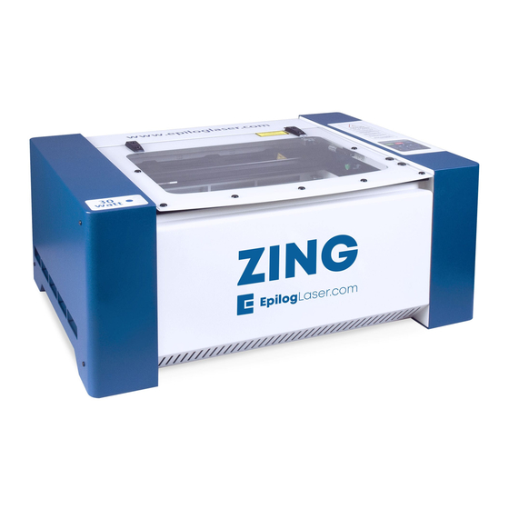
Zing Engraver
Replacing the Control/Display unit
#1 Phillips screw driver
Advertisement
Table of Contents

Related Manuals for Epilog Laser Zing


Summary of Contents for Epilog Laser Zing
- Page 1 16371 Table Mountain Parkway Golden, Colorado 80403 Phone 303-215-9171 - FAX 303-277-9669 www.epiloglaser.com Machine Type: Zing Engraver Procedure: Replacing the Control/Display unit Tools Required: #1 Phillips screw driver NOTE: The control and display units are a single piece. They will be removed and replaced together.
- Page 2 From the Configuration menu you will need to record the following information. To cycle through the Configuration menu, depress the right directional arrow X-Home Y-Home Laser Match Stamp Match System unit Turn off the engraver and disconnect the engraver from its power source. The control assembly is on the right hand side of the machine as you face the machine from the front.
- Page 3 Grasp the screw heads and pull the control unit toward you. This may require a small amount of effort. You are disconnecting electrical connections when you remove the control board as shown in picture 2 Picture 2 Note around the outside of the control housing (picture 3) on the machines chassis, there are small copper strips with fingers that stick up.
- Page 4 On the inside of the control housing there are two small grooves that the control board will fit in to shown in picture 4. Picture 4 Ensure that the tabs on the control fit in to these grooves before pushing the control board in to place as shown in picture 5a and 5b.
Need help?
Do you have a question about the Zing and is the answer not in the manual?
Questions and answers