Table of Contents
Advertisement
Quick Links
IARMOR EDGE™
BEFORE INSTALLATION
REMOVE CONTENTS FROM BOX. VERIFY ALL PARTS ARE
PRESENT. READ INSTRUCTIONS CAREFULLY BEFORE
STARTING INSTALLATION. ASSISTANCE IS RECOMMEND-
ED. THANK YOU FOR CHOOSING OUR PRODUCT!
PART LIST
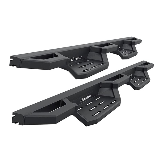
Driver Side Step Bar
x1
Passenger Side Step Bar
x1
Driver Side Mounting Brackets (DFM/DCM/DRM)
x3
Passenger Side Mounting Brackets (PFM/DCM/DRM)
x3
Driver Side Support Brackets (DFS/DCS/DRS)
x3
Passenger Side Support Brackets (PFS/PCS/PRS)
x3
M8 Bolt/Nut Plates
x6
M8 Plastic Washers
x6
M8X1.25-30mm Hex Bolts
x18
M8 Flat Washers
x24
M8 Lock Washers
x12
M8 Bolt/Nut Plate
Plastic Washer
M6X1-25mm
M6 Large
Flat Washer
Hex Bolt
iArmor
M8X
1.25-30mm
Hex Bolt
M6 Flat Washer
M6X1 Nylon
Lock Nut
Customer Support: info@iarmorauto.com
Torque Value
Fastener Size
6mm
8mm
10mm
12mm
14mm
M8X1.25 Nylon Lock Nuts
x6
M8X1.25 Hex Nuts
x6
M6X1-25mm Hex Bolts
x12
M6 Large Flat Washers
x24
M6 X1 Nylon Lock Nuts
x24
M6X1-20mm T-Bolts
x12
M6 Flat Washers
x12
M6X1-20mm T-Bolts (For installing Step Pad)
x32
M6 Flat Washers (For installing Step Pad)
x32
M6 X1 Nylon Lock Nuts (For installing Step Pad)
x32
M6X1-20mm Flat Sunk Head Bolts (For installing Step Pad)
x8
M8 Flat Washer
M8 Lock Washer
M6X1
-20mm
T- Bolt
1
®
PART#: IA‐N208
Tightening Torque (ft-lbs)
6-7
16-18
31-32
56-58
92-94
M8X1.25 Nylon
M8X1.25
Lock Nut
Hex Nut
M6X1
-20mm Flat
Sunk Head Bolt
Rev. 20200401
Advertisement
Table of Contents

Related Manuals for iArmor IARMOR EDGE IA-N208


Summary of Contents for iArmor IARMOR EDGE IA-N208
- Page 1 ® IARMOR EDGE™ PART#: IA‐N208 Torque Value BEFORE INSTALLATION Fastener Size Tightening Torque (ft-lbs) REMOVE CONTENTS FROM BOX. VERIFY ALL PARTS ARE 16-18 PRESENT. READ INSTRUCTIONS CAREFULLY BEFORE 10mm 31-32 STARTING INSTALLATION. ASSISTANCE IS RECOMMEND- 12mm 56-58 ED. THANK YOU FOR CHOOSING OUR PRODUCT!
- Page 2 ® FRONT Passenger Side Step Bar PFS/PCS/PRS Driver Side Step Bar DFM/DCM/DRM PFM/PCM/PRM DFS/DCS/DRS PFS/PCS/PRS DFM/DCM/DRM PFM/PCM/PRM DFS/DCS/DRS Step Pad Step Pad PFS/PCS/PRS DFM/DCM/DRM DFS/DCS/ PFM/PCM/PRM Driver Side Step Bar Assembly Passenger Side Step Bar Assembly Customer Support: info@iarmorauto.com...
- Page 3 ® The instruction here is for your reference only. We strongly STEP 2 recommend the professional installer for best result. We are not responsible for any damage caused by the installation. Starting at the Driver Side Front of the vehicle, remove the sealing tape covering the factory holes in the side of the inner panel, (Fig 1).
- Page 4 ® b. Attach the Driver Side Front Mounting Bracket (DFM/DCM/ DRM) (Fig 6) to the threaded end of the M8 Bolt/Nut Plate with (1) M8 Flat Washer, (1) M8 Lock Washer and (1) M8X1.25 Hex Nut, (Fig 7A). Remove the M8X1.25-30mm Hex Bolt from the nut on the Bolt/Nut Plate from Step 3A.
- Page 5 ® (1)M8X1.25-30mm Hex Bolt (1)M8 Lock Washer Front STEP 4 (1)M8mm Flat Washer Attach the Driver Side Front Support Bracket (DFS/DCS/DRS) to the Driver Side Front Mounting Bracket (DFM/DCM/DRM) with (1)M8x1.25-30mm Hex Bolt, (2)M8 Flat Washers and (1) M8X1.25 Nylon Lock Nut, (Fig 10).
- Page 6 ® Front IMPORTANT: Models w/o STEP 6 holes in pinch weld will re- quire drilling 1/4” holes through pinch weld to attach Move to the Driver Side Rear Mounting location, (Fig 15). Re- Support Brackets. Do com- peat Step 3 to install the Driver Side Rear Mounting Bracket.
- Page 7 ® Front (6)M6X1-20mm T-Bolts (6)M6 Flat Washers (6)M6X1 Nylon Lock Nuts (Fig 17) The Assembled Driver Side Step Bar Installed STEP 8 STEP 9 Properly level and adjust the Step Bar and fully tighten all hard- Move to the passenger side of the vehicle. Repeat Steps 2-8 to ware.
Need help?
Do you have a question about the IARMOR EDGE IA-N208 and is the answer not in the manual?
Questions and answers