Table of Contents
Advertisement
Quick Links
IARMOR EDGE™
BEFORE INSTALLATION
REMOVE CONTENTS FROM BOX. VERIFY ALL PARTS ARE
PRESENT. READ INSTRUCTIONS CAREFULLY BEFORE
STARTING INSTALLATION. ASSISTANCE IS RECOMMEND-
ED. THANK YOU FOR CHOOSING OUR PRODUCT!
*DRILLING NOT REQUIRED
*TRIMMING NOT REQUIRED
PART LIST
DFS/DCS
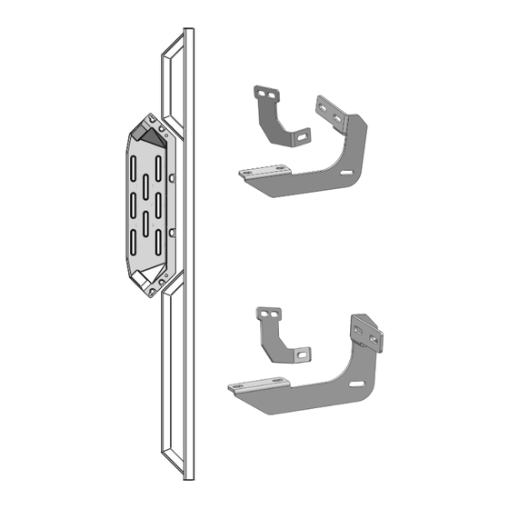
Step Pad
PCB/DRB
Driver Rear Sup-
port Bracket (DRS)
Driver Side Step Bar
iArmor
Driver Front Support
Bracket (DFS/DCS)
Driver Front Mounting
Bracket (DFM)
Driver Center
Mounting Bracket (DCM)
Driver Center Bar
Bracket (DCB/PRB)
Driver Rear Mounting
Bracket (DRM)
Customer Support: www.iarmorauto.com/support
Torque Value
Fastener Size
6mm
8mm
10mm
12mm
14mm
Front
Passenger Front Support
Bracket (PFS/PCS)
Passenger Front
Mounting Bracket
(PFM)
Passenger Center
Mounting Bracket
(PCM)
Passenger Center Bar
Bracket (PCB/DRB)
Passenger Rear Mount-
ing Bracket (PRM)
Passenger Rear Support
Bracket (PRS)
1
®
PART#: IA-N107
Tightening Torque (ft-lbs)
6-7
16-18
31-32
56-58
92-94
PFS/PCS
DCB/PRB
Passenger Side Step Bar
Rev. 20210801
Required
√
√
X
X
X
Step Pad
Advertisement
Table of Contents

Related Manuals for iArmor EDGE


Summary of Contents for iArmor EDGE
- Page 1 ® IARMOR EDGE™ PART#: IA-N107 Torque Value BEFORE INSTALLATION Fastener Size Tightening Torque (ft-lbs) Required REMOVE CONTENTS FROM BOX. VERIFY ALL PARTS ARE √ PRESENT. READ INSTRUCTIONS CAREFULLY BEFORE STARTING INSTALLATION. ASSISTANCE IS RECOMMEND- 16-18 √ ED. THANK YOU FOR CHOOSING OUR PRODUCT!
- Page 2 ® M8X1.25-35 Hex Bolt M8 Large Flat Washer M8X1.25 Nut Plate M8 Flat Washer M8 Lock Washer M8X1.25 Nylon Lock Nut M6X1-25 Hex Bolt M8X1 M8X1.25-20 Inner Hex Bolt .25 Hex Flange Nut M6 Large Flat Washer M6X1 M6X1 Nylon Lock Nut...
- Page 3 ® (Fig 1B) Nut Plate B. Vehicles with factory threaded hole in floor panel: Locate the front ,center and rear mounting locations, (Figs 4 & 5). Continue to Step 3. Pair of holes on pinch weld Front (Fig 1A) Driver Side Front Mounting Location...
- Page 4 ® DFS/DCS STEP 4 On Driver Side Front Mounting Location. Attach the Driver Sup- port Bracket (DFS) on the back of the pinch weld. Secure to (1) M8X1.25-35 Hex Bolt the (2) pairs of holes on the pinch weld with (2) M6X1-25 Hex (2) M8 Flat Washers Bolts, (4) M6 Large Flat Washers &...
- Page 5 ® Fig 13 M8X1.25 Nut Plate Front Front (1) M8X1.25-35 Hex Bolt (1) M8X1.25-35 Hex Bolt (1) M8 Large Flat Washer (1) M8 Large Flat Washer (1) M8 Lock Washer (1) M8 Lock Washer STEP 7 (Fig 11) Driver Front Mounting Bracket Installed...
- Page 6 ® Rear (2) M6x1-25 Hex Bolts DCS/PRS (4) M6 Large Flat Washers (2) M6X1 Nylon Lock Nuts (1) M8X1.25-35 Hex Bolt (1) M8 Large Flat Washer (1) M8 Lock Washer Rear (Fig 19) Driver Rear Support Bracket Mounted to Pinch Weld M8X1.25 Nut Plate...
- Page 7 ® STEP 9 Once (3) driver side brackets are installed, attach the Assembled Driver Side Step Bar on the Mounting Brackets with (2) M6X1-20 T- Bolts, (4) M6X1-20 Square Head Bolts, (6) M6 Flat Washers and (6) M6x1 Nylon Lock Nuts, (Fig 23). Do not fully tighten hardware at this time.
Need help?
Do you have a question about the EDGE and is the answer not in the manual?
Questions and answers