Table of Contents
Advertisement
Quick Links
IARMOR EDGE™
BEFORE INSTALLATION
REMOVE CONTENTS FROM BOX. VERIFY ALL PARTS ARE
PRESENT. READ INSTRUCTIONS CAREFULLY BEFORE
STARTING INSTALLATION. ASSISTANCE IS RECOMMEND-
ED. THANK YOU FOR CHOOSING OUR PRODUCT!
*ROCKER PANEL MOUNT
*DRILLING MAYBE REQUIRED
PART LIST
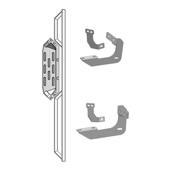
Driver Front Support
Bracket (DFS/PRS)
Driver Rear Support
Bracket (PFS/DRS)
Step Pad
Driver Side Step Bar
iArmor
Front
Driver Front
Mounting
Bracket
(DFM)
Driver Rear Mounting
Bracket (DRM)
Customer Support: info@iarmorauto.com
®
Torque Value
Fastener Size
Tightening Torque (ft-lbs)
6mm
8mm
10mm
12mm
14mm
Passenger Front
Support Bracket
(PFS/DRS)
Passenger
Front
Mounting
Bracket
(PFM)
Passenger Rear Support
Bracket (DFS/PRS)
Passenger Rear Mount-
ing Bracket (PRM)
1
PART#: IA-N178H
Required
6-7
√
16-18
√
31-32
X
56-58
X
92-94
X
Step Pad
Passenger Side Step Bar
Rev. 20220901
Advertisement
Table of Contents

Related Manuals for iArmor EDGE


Summary of Contents for iArmor EDGE
- Page 1 ® IARMOR EDGE™ PART#: IA-N178H Torque Value BEFORE INSTALLATION Fastener Size Tightening Torque (ft-lbs) Required REMOVE CONTENTS FROM BOX. VERIFY ALL PARTS ARE PRESENT. READ INSTRUCTIONS CAREFULLY BEFORE √ STARTING INSTALLATION. ASSISTANCE IS RECOMMEND- 16-18 √ ED. THANK YOU FOR CHOOSING OUR PRODUCT!
- Page 2 ® Hardware Package A (For Brackets & Bars Installation) Item Description Item Description M8 Nylon Lock Nuts M8 Bolt/Nut Plates M8 Plastic Washers M6X1-25 Hex Bolts M8X1.25-30 Hex Bolts M6 Large Flat Washers M8 Flat Washers M6X1 Nylon Lock Nuts M8 Lock Washers M8X1.25-20 T-Bolts...
- Page 3 ® The instruction here is for your reference only. We strongly recommend the professional installer for best result. We are not responsible for any damage caused by the installation. Front STEP 1 Install (4) Pedals onto the step bars with (24) M8X1.25-25mm Hex Bolts, (24) M8 Large Flat Washers and (24) M8 Lock Washers.
- Page 4 ® Flush (Fig 6) Driver Front Mounting Bracket (Fig 3) Thread (1) M8X1.25-30mm Hex Bolt into the nut on the plate. Stop when bolt reaches end of nut as pictured) (1) M8 Flat Washer (1) M8 Lock Washer (1) M8X1.25 Hex Nut M8 Bolt/Nut Plate (Fig 4) Use the loose Hex Bolt as a handle.
- Page 5 ® Models with factory threaded inserts: Line up the slots in the top of the Support Bracket with the (2) factory holes in the pinch weld. Attach the Bracket to the back Attach Driver Front Mounting Bracket to the threaded inserts of the pinch weld with (2) M6X1-25mm Hex Bolts, (4) M6 Large with (2) M8X1.25-30mm Hex Bolts, (2) M8 Lock Washers and...
- Page 6 ® Front IMPORTANT: Models w/o holes in pinch weld will re- STEP 6 quire drilling 1/4” holes through pinch weld to at- tach Support Brackets. Do complete installation of Step Bar first and level Step Bar Once all (2) brackets have been installed, select (4) M8X1.25-...
- Page 7 Bracket. IMPORTANT: Do not drill too close to the bottom edge of the pinch weld. Adjust the Brackets as necessary to move the slots up the body panel away from the edge. Drill the holes toward the outside of the marked slots.
- Page 8 ® (4) M8 Plastic Washers (4) M8X1.25-20mm T-Bolts (4) M8 Flat Washers Front (4) M8 Nylon Lock Nuts Bottom View (Fig 17) Driver Side Step Bar Installation Customer Support: info@iarmorauto.com Rev. 20220901...
Need help?
Do you have a question about the EDGE and is the answer not in the manual?
Questions and answers