Chapters
Table of Contents

Related Manuals for GEM 410


Summary of Contents for GEM 410
- Page 1 Absperrklappe Kunststoff , DN 15 - 100 Butterfl y Valve Plastic, DN 15 - 100 ORIGINAL EINBAU- UND MONTAGEANLEITUNG INSTALLATION, OPERATING AND MAINTENANCE INSTRUCTIONS...
-
Page 2: Table Of Contents
Funktion der GEMÜ-Absperrklappe: Hinweise für Service- Sachgerechter Transport und Lagerung und Bedienpersonal Installation und Inbetriebnahme durch Warnhinweise eingewiesenes Fachpersonal Verwendete Symbole Bedienung gemäß dieser Einbau- und Begriff sbestimmungen Montageanleitung Vorgesehener Einsatzbereich Ordnungsgemäße Instandhaltung Auslieferungszustand Korrekte Montage, Bedienung, Wartung Technische Daten und Reparatur gewährleisten einen... -
Page 3: Hinweise Für Service
VORSICHT (OHNE SYMBOL) die nicht in der Einbau- und Montageanleitung beschrieben sind, Möglicherweise gefährliche Situation! dürfen nicht ohne vorherige Abstimmung ® Bei Nichtbeachtung drohen mit GEMÜ durchgeführt werden. Sachschäden. GEFAHR Sicherheitsdatenblätter bzw. die für die verwendeten Medien geltenden Sicherheitsvorschriften unbedingt... -
Page 4: Verwendete Symbole
Vorgesehener Verwendete Symbole Einsatzbereich Gefahr durch heiße Oberfl ächen! Die Absperrklappe GEMÜ 410 ist für den Einsatz in Rohrleitungen konzipiert. Gefahr durch ätzende Stoff e! Sie steuert ein durchfl ießendes Medium indem sie durch ein Steuermedium geschlossen oder geöff net werden kann. -
Page 5: Technische Daten
Technische Daten Betriebsmedium Zulässige Temperaturen Aggressive, neutrale gasförmige und flüssige Medien, die Umgebungstemperatur +10 ... +60 °C die physikalischen und chemischen Eigenschaften des jeweiligen Körper-, Scheiben- und Dichtwerkstoffs nicht negativ beeinflussen. Max. zul. Druck des Betriebsmediums 6 bar Max. zul. Temp. des Betriebsmediums 60 °C Der zulässige Betriebsdruck ist abhängig von der Temperatur des Kv-Wert... -
Page 6: Bestelldaten
EPDM Bestellbeispiel Nennweite Gehäuseform (Code) Anschlussart (Code) Ventilkörperwerkstoff (Code) Dichtwerkstoff (Code) Steuerfunktion (Code) Antriebsgröße (Code) Zubehör GEMÜ 0324 GEMÜ 1235 GEMÜ 1436 cPos GEMÜ 4222 GEMÜ 1101 Elektrischer Intelligenter Ventilanschaltung mit Vorsteuer- Hubbegrenzung Stellungsrückmelder Stellungs- und integriertem 3/2-Wege- Magnetventil, Prozessregler... -
Page 7: Herstellerangaben
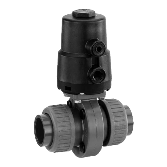
Herstellerangaben Funktionsbeschreibung GEMÜ 410 ist eine zentrische Absperrklappe Transport mit Armaturenverschraubung in den Nennweiten DN 15 - 100. Der Klappenkörper Absperrklappe nur auf geeignetem besteht aus PVC-U, die Klappenscheibe Lademittel transportieren, nicht stürzen, aus PVDF oder PP. Als Dichtwerkstoff e vorsichtig handhaben. -
Page 8: Montage Und Anschluss
(Wasserschläge) durch Verletzungen! Schutzmaßnahmen vermeiden. Bei Arbeiten an der Absperrklappe zuvor Anlage Montagearbeiten nur durch geschultes drucklos schalten und Fachpersonal. Steuermediumleitung(en) der Geeignete Schutzausrüstung gemäß Absperrklappe abschrauben. den Regelungen des Anlagenbetreibers berücksichtigen. Vor Einbau: Installationsort: Eignung Dichtwerkstoff entsprechend Betriebsmedium prüfen. VORSICHT Siehe Kapitel 6 "Technische Daten". -
Page 9: Steuerfunktionen
5. Anlage bzw. Anlagenteil vollständig 5. Überwurfmutter 1 mit Einlegeteil auf entleeren und abkühlen lassen bis Rohrleitung 2 kleben. Verdampfungstemperatur des Mediums 6. O-Ring 3 ggf. wieder einsetzen. unterschritten ist und Verbrühungen 7. Überwurfmutter 1 wieder auf ausgeschlossen sind. Klappenkörper 4 aufschrauben. 6. -
Page 10: Steuermedium Anschließen
Anschluss 4 Anschluss 2 Steuermedium anschließen Blindstopfen 1 entfernen. Bei Steuerfunktion 1 und 2 ist der Anschluss Leitung des Steuermediums 3 4 mit einem Blindstopfen verschlossen. (G 1/4) bei Steuerfunktion 1 und 2 in Steuermediumanschluss 2 des Antriebs Anschlüsse Steuer- einschrauben. -
Page 11: Demontage Absperrklappe (Antrieb Vom Körper Lösen)
Verschmutzungen reinigen (Teile GEFAHR dabei nicht beschädigen). Teile auf Beschädigung prüfen, ggf. Antrieb nicht öff nen! auswechseln (nur Originalteile von ® Gefahr von schwersten Verletzungen GEMÜ verwenden). oder Tod! ® Herstellerhaftung und 12.2 Demontage Absperrdichtung Gewährleistungsanspruch erlischt. Zur Demontage der Zur Demontage des Antriebs Absperrdichtung wird benötigt:... -
Page 12: Montage Absperrdichtung
6. Welle der Scheibe oberhalb und unter- halb der Absperrdichtung einfetten (4). 7. Beide Klappenhälften auseinander drücken. 8. Scheibe mit Absperrdichtung zwischen Klappenhälften einsetzen. 9. Beide Klappenhälften zusammen drücken. 10. Zwei Vierkantmuttern und Abdeckkappe montieren. 11. Innensechskantschrauben einführen Absperrdichtung demontieren und mit Sechskantmuttern über Kreuz handfest anziehen. -
Page 13: Inbetriebnahme
Intervallen demontiert und auf Verschleiß Vor Reinigung bzw. vor Inbetriebnahme geprüft werden. der Anlage: Absperrklappe auf Dichtheit und Funktion Nur Original GEMÜ Ersatzteile prüfen (Absperrklappe schließen und verwenden! wieder öff nen). Beim Bestellen von Ersatzteilen Bei neuen Anlagen und nach... -
Page 14: Demontage
Demontage Rücksendung Demontage erfolgt unter den gleichen Absperrklappe reinigen. Vorsichtsmaßnahmen wie die Montage. Rücksendeerklärung bei GEMÜ Leitung(en) des Steuermediums anfordern. abschrauben (siehe Kapitel 11.3 Rücksendung nur mit vollständig "Steuermedium anschließen"). ausgefüllter Rücksendeerklärung. Absperrklappe demontieren (siehe Ansonsten erfolgt keine Kapitel 12.1 "Demontage Absperrklappe Gutschrift bzw. -
Page 15: Fehlersuche / Störungsbehebung
Fehlersuche / Störungsbehebung Fehler Möglicher Grund Fehlerbehebung Steuerdruck zu niedrig Absperrklappe mit Steuerdruck laut Datenblatt (bei Steuerfunktion NC) betreiben Absperrklappe öff net Steuermedium nicht angeschlossen Steuermedium anschließen nicht bzw. nicht vollständig Antrieb defekt Antrieb wechseln (siehe Kapitel 12.1 und 12.4) Fremdkörper in der Absperrklappe Absperrklappe demontieren und reinigen Absperrklappe mit Betriebsdruck laut... -
Page 16: Schnittbild Und Ersatzteile
Schnittbild und Ersatzteile Pos. Benennung Bestellbezeichnung Klappenkörper komplett K410 Absperrdichtung 410…P02… Klappenscheibe PVDF (DN 15-50) 410...P03 20 Klappenscheibe PP (DN 65-100) 410...P03 5 Abdeckkappe 410…P07… O-Ring 410…P01 13… Einlegeteil 410…P01 14… Überwurfmutter 410…P01 15… Schraube 410...S30… Scheibe Antrieb 9415... 16 / 36... -
Page 17: Einbauerklärung
4.1.2.6. b); 4.1.2.6. c); 4.1.2.6. d); 4.1.2.6. e); 4.1.3.; 4.2.1.; 4.2.1.4.; 4.2.2.; 4.2.3.; 4.3.1.; 4.3.2.; 4.3.3.; 4.4.1.; 4.4.2.; 5.3.; 5.4.; 6.1.1.; 6.3.3.; 6.4.1.; 6.4.3. Ferner wird erklärt, dass die speziellen technischen Unterlagen gemäß Anhang VII Teil B erstellt wurden. Es wird ausdrücklich erklärt, dass die unvollständige Maschine allen einschlägigen Bestimmungen... -
Page 18: Eg-Konformitätserklärung
Die Produkte werden entwickelt und produziert nach GEMÜ eigenen Verfahrensanweisungen und Qualitätsstandards, welche die Forderungen der ISO 9001 und der ISO 14001 erfüllen. Die Produkte dürfen gemäß Artikel 3, Absatz 3 der Druckgeräterichtlinie 97/23/EG keine CE- Kennzeichnung tragen. Joachim Brien... - Page 19 Contents General information General information Prerequisites to ensure that the GEMÜ General safety information butterfl y valve functions correctly: Information for service Correct transport and storage and operating personnel Installation and commissioning by trained Warning notes personnel Symbols used Operation according to these installation, Defi...
-
Page 20: Information For Service And Operating Personnel
fi rst. DANGER Strictly observe the safety data sheets or the safety regulations that are valid for the media used. In cases of uncertainty: Consult the nearest GEMÜ sales offi ce. 20 / 36... -
Page 21: Symbols Used
Control medium to customer The medium whose increasing or decreasing pressure causes the butterfl y The GEMÜ butterfl y valve is supplied as a valve to be actuated and operated. separately packed component. Control function The possible actuation functions of the butterfl... -
Page 22: Technical Data
Technical data Working medium Admissible temperatures Inert, corrosive gaseous and liquid media which have no Ambient temperature +10 ... +60 °C negative impact on the physical and chemical properties of the body, disc and seal materials Max. perm. pressure of working medium 6 bar Max. -
Page 23: Order Data
Connection (Code) Valve body material (Code) Seal material (Code) Control function (Code) Actuator size (Code) Accessories GEMÜ 0324 GEMÜ 1101 GEMÜ 1235 GEMÜ 1436 cPos GEMÜ 4222 Pilot Solenoid Stroke limiter Electrical Intelligent Positioner Combi switchbox Valve, Plastic Position Indicator... -
Page 24: Manufacturer's Information
Manufacturer’s information Functional description GEMÜ 410 is a centric butterfl y valve Transport with union ends in the nominal sizes DN 15 - 100. The butterfl y valve body is made Only transport the butterfl y valve by from PVC-U, the disk from PVDF or PP. -
Page 25: Installation And Connection
Installation and connection Installation work must only be performed by trained personnel. DANGER Use appropriate protective gear as specifi ed in plant operator's guidelines. Danger - maiming! ® Danger of severe injuries! Installation location: Depressurize the plant and disconnect the control CAUTION medium line(s) to the butterfl... -
Page 26: Control Functions
Installation - Union ends with insert: 8. Connect the other side of the butterfl y valve body 5 to the piping 2, too. CAUTION Observe appropriate regulations for Damage to the butterfl y valve! connections! ® Only use solvent cement suitable for the butterfl... -
Page 27: Connecting The Control Medium
Connector 4 Connector 2 Connecting the control medium Remove blanking plug 1. Control function 1 and 2: connector 4 is For control function 1 and 2 screw the closed with a blanking plug. connector of the control medium 3 (G 1/4) into control medium connector 2 of the Connectors Control... -
Page 28: Butterfly Valve Disassembly (Removing Actuator From Body)
(do not damage parts). Check parts for potential DANGER damage, replace if necessary (only use genuine parts from GEMÜ). Do not open the actuator! ® Danger of severe injuries or death! 12.2 Disassembly of the shut-off ® The manufacturer's liability and seal guarantee will be voided. -
Page 29: Assembling The Shut-Off Seal
7. Press open the two halves of the butterfl y valve. 8. Insert disc with shut-off seal between the two halves of the butterfl y valve. 9. Press together the two halves of the butterfl y valve. 10. Assemble the two square nuts and caps. 11. -
Page 30: Commissioning
(water hammer). wear. Prior to cleaning or commissioning the Use only genuine GEMÜ spare plant: parts! Check the tightness and the function of When ordering spare parts, the butterfl y valve (close and reopen the specify the complete order butterfl... -
Page 31: Disassembly
Disconnect the control medium line(s) Returns must be made with a completed (see chapter 11.3 "Connecting the control declaration of return. medium"). If not completed, GEMÜ cannot process Disassemble the butterfl y valve (see credits or chapter 12.1 "Butterfl y valve disassembly repair work (removing actuator from body)"). -
Page 32: Troubleshooting / Fault Clearance
Troubleshooting / Fault clearance Fault Possible cause Fault clearance Control pressure too low Operate butterfl y valve with control pressure (for control function NC) specifi ed in data sheet The butterfl y valve does not open Control medium not connected Connect control medium or doesn't open Actuator is faulty... -
Page 33: Sectional Drawing And Spare Parts
Sectional drawing and spare parts Item Name Order description Butterfl y valve body complete K410 Shut-off seal 410…P02… Butterfl y disc PVDF (DN 15-50) 410...P03 20 Butterfl y disc PP (DN 65-100) 410...P03 5 410…P07… O-ring 410…P01 13… Insert 410…P01 14… Union nut 410…P01 15…... -
Page 34: Declaration Of Incorporation
Declaration of Incorporation according to the EC Machinery Directive 2006/42/EC, Annex II, 1.B for partly completed machinery Manufacturer: GEMÜ Gebr. Müller Apparatebau GmbH & Co. KG Postfach 30 Fritz-Müller-Straße 6-8 D-74653 Ingelfingen-Criesbach Description and identification of the partly completed machinery: Make: GEMÜ... -
Page 35: Ec Declaration Of Conformity
Module H Note for equipment with a nominal size ≤ DN 25: The products are developed and produced according to GEMÜ process instructions and quality standards which comply with the requirements of ISO 9001 and of ISO 14001. According to section 3, paragraph 3 of the Pressure Equipment Directive 97/23/EC these products must not be identified by a CE-label. - Page 36 VENTIL-, MESS- UND REGELSYSTEME VALVES, MEASUREMENT AND CONTROL SYSTEMS GEMÜ Gebr. Müller Apparatebau GmbH & Co. KG · Fritz-Müller-Str. 6-8 · D-74653 Ingelfi ngen-Criesbach Telefon +49(0)7940/123-0 · Telefax +49(0)7940/123-192 · info@gemue.de · www.gemu-group.com...
Need help?
Do you have a question about the 410 and is the answer not in the manual?
Questions and answers