GEM 695 Operating Instructions Manual
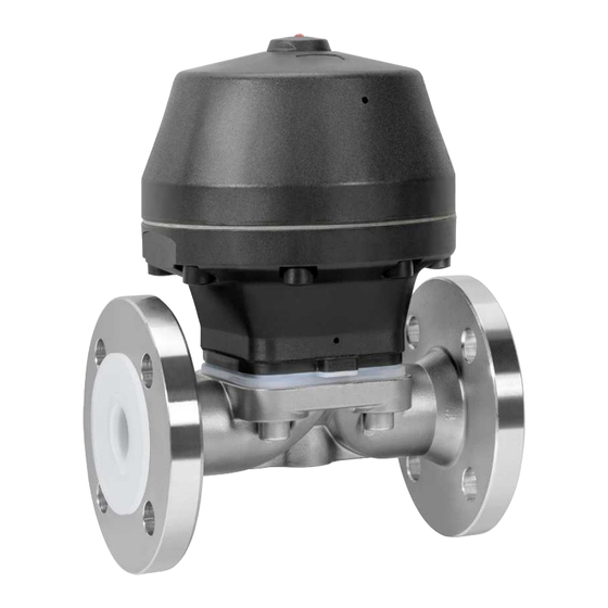
Pneumatically operated diaphragm valve
Hide thumbs
Also See for 695:
- Installation, operating and maintenance instructions (44 pages) ,
- Operating instructions manual (44 pages)

Related Manuals for GEM 695


Summary of Contents for GEM 695
- Page 1 GEMÜ 695 Pneumatically operated diaphragm valve Operating instructions further information webcode: GW-695...
- Page 2 All rights including copyrights or industrial property rights are expressly reserved. Keep the document for future reference. © GEMÜ Gebr. Müller Apparatebau GmbH & Co. KG 25.04.2023 GEMÜ 695 2 / 40 www.gemu-group.com...
-
Page 3: Table Of Contents
20 Declaration of Incorporation according to the EC Function ............Machinery Directive 2006/42/EC, Annex II, 1.B ..Product label ..........21 Declaration of Conformity according of the Direct- 4 GEMÜ CONEXO ............ ive 2014/68/EU ............ 5 Correct use ............6 Order data ............Order codes ........... -
Page 4: General Information
1.3 Definition of terms Imminent danger! ▶ Non-observance can cause death or Working medium severe injury. The medium that flows through the GEMÜ product. Control function The possible actuation functions of the GEMÜ product. WARNING Control medium Potentially dangerous situation! The medium whose increasing or decreasing pressure causes ▶... -
Page 5: Safety Information On The Product ............... 5 18 Disposal
Tá an cochall faoi lingeán-bhrú It-tapp huwa ppressat b’molla turer first. Motorkap staat onder veerdruk In cases of uncertainty: 15. Consult the nearest GEMÜ sales office. www.gemu-group.com 5 / 40 GEMÜ 695... -
Page 6: Product Description
Item Name Materials The month of manufacture is encoded in the traceability num- Position indicator ber and can be obtained from GEMÜ. The product was manu- Membrane actuator PP, glass fibre reinforced factured in Germany. Diaphragm EPDM PTFE/EPDM (one-piece, two-... -
Page 7: Correct Use
The CONEXO portal acts as a central element, helping to collect, manage and process all data. For further information on GEMÜ CONEXO please visit: www.gemu-group.com/conexo 5 Correct use DANGER Danger of explosion! ▶... -
Page 8: Order Data
FTF MSS SP-88, length only for body configuration D Flange ANSI Class 125/150 RF, EPDM face-to-face dimension FTF EN 558 series 1, ISO 5752, EPDM basic series 1, EPDM length only for body configuration D EPDM GEMÜ 695 8 / 40 www.gemu-group.com... - Page 9 Ra max. 0.51 µm (20 µin.) for media wetted surfaces, in accordance with ASME BPE SF1, mechanically polished internal Ra max. 0.64 µm (25 µin.) for media wetted surfaces, in accordance with ASME BPE SF2, mechanically polished internal www.gemu-group.com 9 / 40 GEMÜ 695...
-
Page 10: Order Example
8 Actuator version Actuator size FDN 9 Surface 1500 Ra ≤ 6.3 μm (250 μin.) for media wetted surfaces, mechanically polished internal 10 Special version Special version for oxygen, maximum medium temperature: 60 °C 11 CONEXO Without GEMÜ 695 10 / 40 www.gemu-group.com... -
Page 11: Technical Data
-10 — 80 °C 0 — 60 °C PTFE/FKM (code 5T) -10 — 80 °C Ambient temperature: 0 — 60 °C Control medium temper- 0 — 40 °C ature: Storage temperature: 0 — 40 °C www.gemu-group.com 11 / 40 GEMÜ 695... -
Page 12: Pressure
For control function 3 (without lifting spring) control pressure is approx. 1 bar lower. The control pressure depending on the prevailing operating pressure, as shown in the diagram, is intended as a guide for operating the system with low wear on the diaphragm. GEMÜ 695 12 / 40 www.gemu-group.com... - Page 13 Therefore the Kv values may exceed the tolerance limits of the standard. The Kv value curve (Kv value dependent on valve stroke) can vary depending on the diaphragm material and dur- ation of use. www.gemu-group.com 13 / 40 GEMÜ 695...
-
Page 14: Product Conformity
0.55 0.39 0.90 0.79 2.80 0.63 1.45 0.88 1.40 1.66 3.40 1.62 1.32 0.93 1.90 1.62 4.50 1.50 2.25 1.56 2.70 2.70 6.30 2.50 2.20 10.30 2.30 MG = diaphragm size, weight in kg GEMÜ 695 14 / 40 www.gemu-group.com... -
Page 15: Dimensions
146.0 28.0 G 1/4 HDM, HDN 171.0 197.0 52.0 G 1/4 JDM, JDN 211.0 245.0 90.0 G 1/4 Dimensions in mm MG = diaphragm size * CT = A + H1 (see body dimensions) www.gemu-group.com 15 / 40 GEMÜ 695... - Page 16 G 1/4 HDM, HDN 171.0 162.0 52.0 55.0 G 1/4 JDM, JDN 211.0 206.0 90.0 48.0 G 1/4 Dimensions in mm MG = diaphragm size * CT = A + H1 (see body dimensions) GEMÜ 695 16 / 40 www.gemu-group.com...
-
Page 17: Body Dimensions
Code 17: Spigot EN 10357 series A/DIN 11866 series A formerly DIN 11850 series 2 Code 60: Spigot ISO 1127/EN 10357 series C/DIN 11866 series B 2) Valve body material Code C3: 1.4435, investment casting www.gemu-group.com 17 / 40 GEMÜ 695... - Page 18 173.0 1.65 2½" 30.0 63.50 173.0 1.65 Dimensions in mm MG = diaphragm size 1) Connection type Code 59: Spigot ASME BPE/DIN 11866 series C 2) Valve body material Code C3: 1.4435, investment casting GEMÜ 695 18 / 40 www.gemu-group.com...
- Page 19 Code 37: Spigot SMS 3008 2) Valve body material Code 40: 1.4435 (F316L), forged body Code 42: 1.4435 (BN2), forged body, Δ Fe < 0.5% Code C3: 1.4435, investment casting Code F4: 1.4539, forged body www.gemu-group.com 19 / 40 GEMÜ 695...
- Page 20 Dimensions in mm MG = diaphragm size n = number of flats 1) Connection type Code 1: Threaded socket DIN ISO 228 2) Valve body material Code 37: 1.4408, investment casting Code 90: EN-GJS-400-18-LT (GGG 40.3) GEMÜ 695 20 / 40 www.gemu-group.com...
- Page 21 Dimensions in mm MG = diaphragm size n = number of flats 1) Connection type Code 31: NPT female thread 2) Valve body material Code 37: 1.4408, investment casting Code 90: EN-GJS-400-18-LT (GGG 40.3) www.gemu-group.com 21 / 40 GEMÜ 695...
- Page 22 Dimensions in mm MG = diaphragm size 1) Connection type Code 6: Threaded spigot DIN 11851 2) Valve body material Code 40: 1.4435 (F316L), forged body Code 42: 1.4435 (BN2), forged body, Δ Fe < 0.5% GEMÜ 695 22 / 40 www.gemu-group.com...
- Page 23 MG = diaphragm size 1) Connection type Code 6K: Cone spigot and union nut DIN 11851 2) Valve body material Code 40: 1.4435 (F316L), forged body Code 42: 1.4435 (BN2), forged body, Δ Fe < 0.5% www.gemu-group.com 23 / 40 GEMÜ 695...
- Page 24 Code 40: 1.4435 (F316L), forged body Code 42: 1.4435 (BN2), forged body, Δ Fe < 0.5% Code 83: EN-GJS-400-18-LT (GGG 40.3), hard rubber lined Code 90: EN-GJS-400-18-LT (GGG 40.3) Code C3: 1.4435, investment casting GEMÜ 695 24 / 40 www.gemu-group.com...
- Page 25 Code 40: 1.4435 (F316L), forged body Code 42: 1.4435 (BN2), forged body, Δ Fe < 0.5% Code 83: EN-GJS-400-18-LT (GGG 40.3), hard rubber lined Code 90: EN-GJS-400-18-LT (GGG 40.3) Code C3: 1.4435, investment casting www.gemu-group.com 25 / 40 GEMÜ 695...
- Page 26 Code 8T: Clamp DIN 32676 series C, face-to-face dimension FTF EN 558 series 7, length only for body configuration D 2) Valve body material Code 40: 1.4435 (F316L), forged body Code 42: 1.4435 (BN2), forged body, Δ Fe < 0.5% Code F4: 1.4539, forged body GEMÜ 695 26 / 40 www.gemu-group.com...
-
Page 27: Manufacturer's Information
▶ Risk of slipping-off 4. Do not store solvents, chemicals, acids, fuels or similar Choose the installation location so that the product can- fluids in the same room as GEMÜ products and their spare ● not be used as a foothold. -
Page 28: Installation Position
3. Insert the corresponding gasket between the body of the product and the pipe connection. 4. Connect the gasket between the body of the product and the pipe connection using clamps. 5. Re-attach or reactivate all safety and protective devices. GEMÜ 695 28 / 40 www.gemu-group.com... -
Page 29: Installation With Threaded Spigots
Control function 3 Double acting (DA): Valve resting position: no defined normal position. The valve is opened and closed by activating the respective control me- dium connectors (connector 2: open/connector 4: close). www.gemu-group.com 29 / 40 GEMÜ 695... -
Page 30: Connecting The Control Medium
(water hammer). CAUTION The product has 2 control medium connectors. Cleaning agent ▶ Damage to the GEMÜ product. Control function Control medium Control medium The plant operator is responsible for selecting the clean-... -
Page 31: Control Function 1
In its resting position the product has no defined normal posi- tion. 1. Activate the actuator via control medium connector 2. ð The product opens. 2. Activate the actuator via control medium connector 4. ð The product closes. www.gemu-group.com 31 / 40 GEMÜ 695... -
Page 32: Troubleshooting
Tighten threaded connections / unions Sealing material faulty Replace sealing material Valve body leaking Valve body leaking or corroded Check valve body for damage, replace valve body if necessary * see chapter "Spare parts" GEMÜ 695 32 / 40 www.gemu-group.com... -
Page 33: Inspection And Maintenance
3. Shut off plant or plant component. 4. Secure the plant or plant component against recommis- sioning. 5. Depressurize the plant or plant component. 6. Actuate GEMÜ products which are always in the same po- sition four times a year. www.gemu-group.com 33 / 40... -
Page 34: Removing The Diaphragm
2. Clean all parts of contamination (do not damage parts dur- ing cleaning). 3. Check parts for potential damage, replace if necessary (only use genuine parts from GEMÜ). 16.2.3 Mounting the diaphragm NOTICE ▶ Fit the diaphragms suitable for the product (suitable for medium, medium concentration, temperature and pres- sure). - Page 35 5. Position the new backing diaphragm onto the compressor. 8. With the valve fully assembled, check the function and 6. Position the diaphragm face onto the backing diaphragm. tightness. 7. Screw diaphragm face tightly into the compressor manu- ally. www.gemu-group.com 35 / 40 GEMÜ 695...
-
Page 36: Tion 1
4. Disassemble the product. Observe warning notes and safety information. 18 Disposal 1. Pay attention to adhered residual material and gas diffu- sion from penetrated media. 2. Dispose of all parts in accordance with the disposal regu- lations/environmental protection laws. GEMÜ 695 36 / 40 www.gemu-group.com... - Page 37 Returned goods can be processed only when this note is completed. If no return delivery note is included with the product, GEMÜ cannot process credits or repair work but will dispose of the goods at the operator's expense.
-
Page 38: Machinery Directive 2006/42/Ec, Annex Ii, 1.B
Declaration of Incorporation according to the EC Machinery Directive 2006/42/EC, Annex II, 1.B for partly completed machinery Manufacturer: GEMÜ Gebr. Müller Apparatebau GmbH & Co. KG Postfach 30 Fritz-Müller-Straße 6-8 D-74653 Ingelfingen-Criesbach Description and identification of the partly completed machinery: Make: GEMÜ... - Page 39 Module H1 Note for equipment with a nominal size ≤ DN 25: The products are developped and produced according to GEMÜ process instructions and quality standards which comply with the requirements of ISO 9001 and of ISO 14001. According to section 4, paragraph 3 of the Pressure Equipment Directive 2014/68/EU these products must not be identified by a CE-label.
- Page 40 GEMÜ Gebr. Müller Apparatebau GmbH & Co. KG Fritz-Müller-Straße 6-8, 74653 Ingelfingen-Criesbach, Germany Subject to alteration Phone +49 (0) 7940 1230 · info@gemue.de www.gemu-group.com 04.2023 | 88245879...
Need help?
Do you have a question about the 695 and is the answer not in the manual?
Questions and answers