Table of Contents
Advertisement
Quick Links
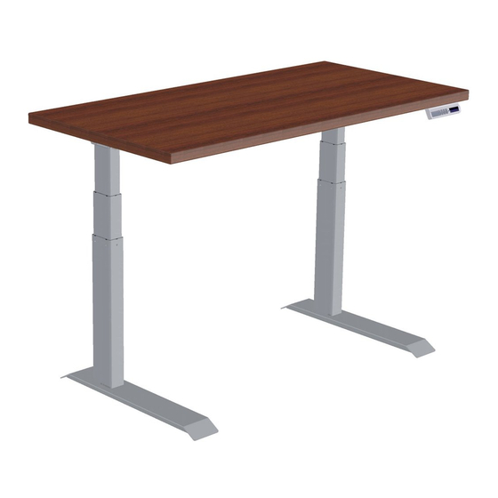
Assembly & Installation Instructions:
Fundamentals 2-Leg Workcenter FDEX30-48-X
Parts Included, Frame Set
A
Control Leg
Qty: 1
Companion Leg
Box 2
B
B
Companion Leg
Companion Leg
Qty: 1
Qty: 1
Required & Sold Separately
Foot Kit
Basic or Programmable Control
Worksurface
C
Short Bracket
Qty: 4
D
Left End Bracket
Qty: 1
Hardware kit, 4225338 (Silver and White) or 4225339 (Charcoal)
F
#M6 × 14 mm Flat Head Cap
Screw
Qty: 20
G
4 mm Allen Wrench
Qty: 1
H
#12 × ¾" Pan Head Laminate
Top Screw
Qty: 26
E
Right End Bracket
Qty: 1
I
Feet Glides
Qty: 4
J
Cable Spool
Qty: 1
K
Cable Loops
Qty: 5
M
Leg Cable - 2 meter
Qty: 1
N
Power cord - 3.5 meters
Qty: 1
O
Power Supply
Qty: 1
L
#8 × ⅝" Pan Head Screw
Qty: 7
Box 1
Advertisement
Table of Contents

Related Manuals for Workrite Ergonomics FDEX30-48-X


Summary of Contents for Workrite Ergonomics FDEX30-48-X
- Page 1 Assembly & Installation Instructions: Fundamentals 2-Leg Workcenter FDEX30-48-X Parts Included, Frame Set Box 1 Control Leg Short Bracket Right End Bracket Leg Cable - 2 meter Qty: 1 Qty: 4 Qty: 1 Qty: 1 Left End Bracket Power cord - 3.5 meters...
- Page 2 Loading should be evenly distributed over table surfaces. “Payload Capacity” is the Workrite Ergonomics recommended maximum loading which includes the Workrite sourced table top.
- Page 3 Note: the right leg will be on your left and vice versa when the assembly is seen upside down. Hardware at actual size #M6 × 14 mm Flat Head Right (Control) leg Left (Companion) leg Cap Screw front Workrite Ergonomics | 800.959.9675 www.workriteergo.com 3 of 8...
- Page 4 Tighten all screws connecting brackets to leg assemblies. Skip to Step 5. Hardware at actual size #12 × ¾" Pan Head Laminate Top Screw 4 of 8 Workrite Ergonomics | 800.959.9675 www.workriteergo.com...
- Page 5 Screws (H). If you use an electric screwdriver, be Bracket (D & E) sure it is on the lowest torque setting to avoid stripping the holes in the top. Needs feet attached Tighten all screws connecting brackets to leg assemblies. Workrite Ergonomics | 800.959.9675 www.workriteergo.com 5 of 8...
- Page 6 #8 × ⅝"Pan Head Screw (L) making sure to wrap the Cable Loop around the cables prior to attaching. If you DO NOT have a Workrite worksurface, mount cable spools in a convenient location between legs and control box. Programmable Control shown 6 of 8 Workrite Ergonomics | 800.959.9675 www.workriteergo.com...
- Page 7 Insert the Power Cord (N) into the two position connector labeled “DC” on the Control Leg. Insert the Control Cable into the data connector labeled “A1” on the Control Leg. Control Cable Control Leg Companion Leg Control Cable Workrite Ergonomics | 800.959.9675 www.workriteergo.com 7 of 8...
- Page 8 To clean the legs, apply cleaner to a soft cloth. Suggested cleaners: Windex or Formula 409. Do not use solvents and do not saturate or spray cleaners directly to table base. 8 of 8 Workrite Ergonomics | 800.959.9675 www.workriteergo.com #1500211- Rev B...
Need help?
Do you have a question about the FDEX30-48-X and is the answer not in the manual?
Questions and answers