Advertisement
Quick Links
Assembly & Installation Instructions:
Fundamentals 3-Leg Workcenter FDEX/FDLX5472-4272EOC
Parts Included, Frame Set
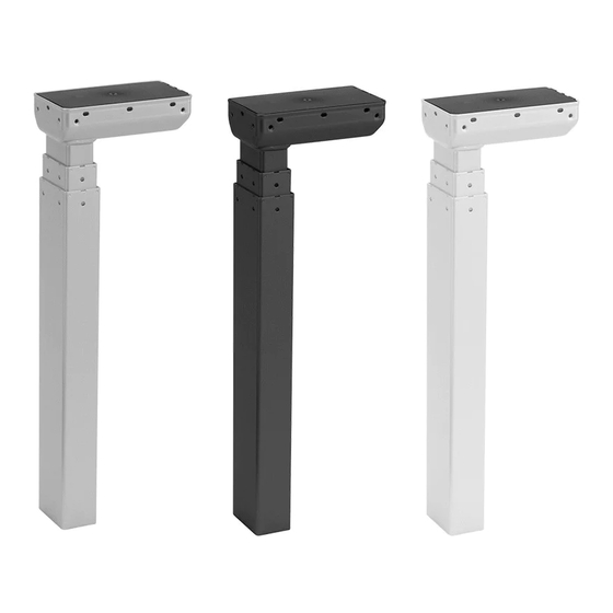
A
Leg
Qty: 3
Hardware Kit
D
#M6 × 12 mm Flat Head
Cap Screw
Qty: 12
E
Short Bracket
Qty: 3
F
Left End Bracket
Qty: 1
G
Right End Bracket
Qty: 1
0.4126 "
H
Corner End Bracket
Qty: 1
Required & Sold Separately
Worksurface
Workrite Ergonomics | (800) 959–9675 www.workriteergo.com
B
Rear Bracket
Qty:3
C
Connector Bracket
Qty: 2
I
#M6 × 14 mm Flat Head
Cap Screw
Qty: 36
J
4 mm Allen Wrench
Qty: 1
K
#12 × ¾" Pan Head
Laminate Top Screw
Qty: 61
L
Corner Foot
Qty: 1
0.134"
3/4"
0.216"
#12 Screw Size
#3 Drive
M
Foot Glides
Qty: 5
V
Programmable
Control
Qty: 1
W
Feet
Qty: 2
N
#12 x 2" Flat Head Screw
Qty: 2
O
Control Box
Qty: 1
P
Cable Spool
Qty: 3
Q
³⁄ 1 6" Cable Loops
Qty: 15
R
#8 × ⅝" Pan Head Screw
Qty: 18
S
Leg Cable, 1 Meter
Qty: 2
T
Leg Cable, 2 Meters
Qty: 1
U
Power cord
Qty: 1
Box 1
1 of 12
Advertisement

Subscribe to Our Youtube Channel
Related Manuals for Workrite Ergonomics FDLX5472-4272EOC


Summary of Contents for Workrite Ergonomics FDLX5472-4272EOC
- Page 1 0.4126 " 0.134" 3/4" 0.216" #12 Screw Size #3 Drive Foot Glides Corner End Bracket #8 × ⅝" Pan Head Screw Qty: 5 Qty: 1 Qty: 18 Required & Sold Separately Worksurface Workrite Ergonomics | (800) 959–9675 www.workriteergo.com 1 of 12...
- Page 2 Loading should be evenly distributed over table surfaces. “Payload Capacity" is the Workrite Ergonomics recommended maximum loading which includes the Workrite sourced table top. Fundamentals 3-LEG V = 120 VAC, 60 Hz / 3.3 A maximum...
- Page 3 Head Cap Screw (D) for assembly. Note: Brackets can be sized in 3" When shown upside down, right will be on your left and vice-versa. Your frameset may differ. increments for any non-Workrite top. Workrite Ergonomics | (800) 959–9675 www.workriteergo.com 3 of 12...
- Page 4 Cap Screw (D) for assembly. Note: Brackets can be sized in 3" increments for any When shown upside down, right will be on your left and vice-versa. Your frameset may differ. non-Workrite top. 4 of 12 Workrite Ergonomics | (800) 959–9675 www.workriteergo.com...
- Page 5 Left End Bracket Note: The Right End Bracket (G) will be on Left configuration your left when wupside down. Note: Left configurations will assemble as a mirror image of these instructions. Workrite Ergonomics | (800) 959–9675 www.workriteergo.com 5 of 12...
- Page 6 (2 installed in step 5.2) 18 screws per Connected Rear Bracket 6 or 12 screws per Floating Rear Bracket 3 screws per Short Bracket 2 screws per End Bracket (2 installed in step 5.2) 6 of 12 Workrite Ergonomics | (800) 959–9675 www.workriteergo.com...
- Page 7 (2 installed in step 6.3) 18 screws per 6 or 12 screws per Connected Rear Bracket Floating Rear Bracket* 3 screws per Short Bracket 2 screws per End Bracket (2 installed in step 6.3) Workrite Ergonomics | (800) 959–9675 www.workriteergo.com 7 of 12...
- Page 8 8.3 Plug Power Cord (U) into power outlet AC on the Control Box (O). 8.4 Plug Leg Cable (S) into port “3” on the Control Box. 8.5 Lay the Control Box down in installation location with cables in place. 8 of 12 Workrite Ergonomics | (800) 959–9675 www.workriteergo.com...
- Page 9 9.4 Lay out Leg Cables (S & T) to be sure they all reach the Control Box. Hardware at actual size Hardware at actual size #12 × 2" Flat Head Screw #12 × ¾" Pan Head Laminate Top Screw Workrite Ergonomics | (800) 959–9675 www.workriteergo.com 9 of 12...
- Page 10 Note the additional P-Loop and Cable Spool locations that may provide better attachment and routing options for your specific configuration. Hardware at actual size #8 × ⅝" Pan Head Screw 10.1 10.2 10.2 10.1 10.1 Switch Cable 10 of 12 Workrite Ergonomics | (800) 959–9675 www.workriteergo.com...
- Page 11 11.4 Connect 2 Meter Leg Cable (T) to the port on the Left Leg (A) then to port “2” on the Control Box (O) 11.2 11.4 11.1 11.4 11.2 11.4 Installed in Step 9 11.1 Switch Cable into 11.3 Switch Port “A1” Workrite Ergonomics | (800) 959–9675 www.workriteergo.com 11 of 12...
- Page 12 Suggested cleaners: Windex or Formula 409. Do not use solvents and do not saturate or spray cleaners directly to workcenter base. ✓ Replacement Parts Visit http://workriteergo.com/documentation/other/workrite_ergonomics_pricing_specification_guide.pdf replacement parts. 12 of 12 Workrite Ergonomics | (800) 959–9675 www.workriteergo.com #1500417 Rev A...
Need help?
Do you have a question about the FDLX5472-4272EOC and is the answer not in the manual?
Questions and answers