Advertisement
Quick Links
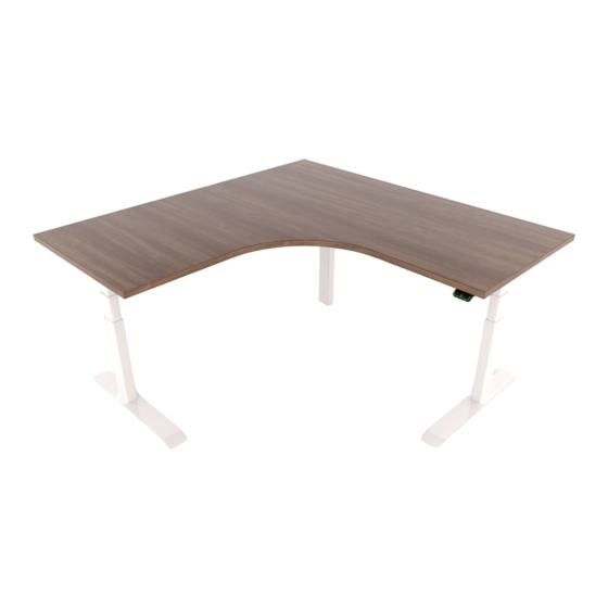
Assembly & Installation Instructions:
Sentinel Electric 54"–72" Base
ST2E-5472-4272EOC-XXX-XX-X, ST3E-5472-4272EOC-XXX-XX-X
Parts Included
A
Electric Leg Assembly
w/Cable
Qty: 3
B
Switch (Standard, Programmable,
or Bluetooth)
Qty: 1
C
DMP360 Power Supply
Qty: 1
D
DMP360 Power Supply
Power Cord
Qty: 1
E
1 Meter Motor Cable
Extension
Qty: 1
F
Left Motor Bracket
Qty: 1
G
Right Motor Bracket
Qty: 1
Worksurface Required, Sold Separately:
Equal Corners
24" Feet
30" Feet
Left Offset Corners
24" Feet
30" Feet
Right Offset Corners
24" Feet
30" Feet
Workrite Ergonomics | 800.959.9675 www.workriteergo.com
H
Short Motor Bracket
Qty: 3
I
Corner Motor Bracket
Qty: 1
J
Rear Bracket
Qty: 3
K
Connector Bracket
Qty: 2
L
Long Foot
Qty: 2
M
Corner Foot
Qty: 1
N
M6 × 1.0P × 12 mm
Flat Head Allen Screw
Qty: 16
O
M8 × 1.25P × 20 mm
Flat Head Allen Screw
Qty: 6
Width Left
Width Right
58–72"
58–72"
58–72"
58–72"
Width Left
Width Right
58–72"
46–60"
58–72"
46–60"
Width Left
Width Right
46–60"
58–72"
46–60"
58–72"
P
Q
R
S
T
U
V
W
X
Tools Required:
Depth
23–24"
29–30"
Depth
Cordless Drill
23–24"
29–30"
Depth
⅛" pilot drill bit
23–24"
29–30"
#8 × ⅝" Phillips Pan
Head Screw
Qty: 17
#12 × ¾" Phillips Pan
Head Screw
Qty: 61
Cable Spool
Qty: 3
P-Loop
Qty: 15
4 mm Allen Wrench
Qty: 1
5 mm Allen Wrench
Qty: 1
Glide
Qty: 4
Corner Glide
Qty: 1
Corner Glide Adjuster
Qty: 1
#2 Phillips Bit
#3 Phillips Bit
Screwdriver or
Screwdriver or
Driver/Drill
Driver/Drill
" pilot drill bit
⁄
3
32
pencil
1 of 11
Advertisement

Related Manuals for Workrite Ergonomics ST2E-5472-4272EOC Series


Summary of Contents for Workrite Ergonomics ST2E-5472-4272EOC Series
- Page 1 30" Feet 58–72" 46–60" 29–30" Right Offset Corners Width Left Width Right Depth ⅛" pilot drill bit " pilot drill bit ⁄ 24" Feet 46–60" 58–72" 23–24" pencil 30" Feet 46–60" 58–72" 29–30" Workrite Ergonomics | 800.959.9675 www.workriteergo.com 1 of 11...
-
Page 2: Important Safety Instructions
In some cases, the images in this instruction may not match the power cord supplied with your electrical furnishing based on your region. Figure C Plug type, blade size, and shape may change. 2 of 11 Workrite Ergonomics | 800.959.9675 www.workriteergo.com... - Page 3 NOTE! Only use the #M6 × 1.0P × 12 mm flat head Allen screw (N) for assembly. 61" 55" 49" 70" Work centers 43" 64" Work centers 52" & 58" Work centers Workrite Ergonomics | 800.959.9675 www.workriteergo.com 3 of 11...
- Page 4 Note: Brackets can be sized Floating Side, Floating Side, in 3" increments for any Left Configuration Right Configuration non-Workrite top. When shown upside down, right will be on your left and vice-versa. Your frameset may differ. 4 of 11 Workrite Ergonomics | 800.959.9675 www.workriteergo.com...
- Page 5 Allen wrench (T). Corner Leg Connected Floating Stretcher Stretcher Left Leg Right Leg Bracket Bracket Hardware at actual size M6 × 1.0P × 12 mm Flat Head Allen Screw Workrite Ergonomics | 800.959.9675 www.workriteergo.com 5 of 11...
- Page 6 Using the ⅛” drill bit, drill ¾” deep pilot holes in the #12 × ¾" Phillips Pan Head remainig locations in the brackets on the legs. Screws Install #12 × ¾" Phillips pan head screws (Q) into all pilot holes and tighten securely. 6 of 11 Workrite Ergonomics | 800.959.9675 www.workriteergo.com...
-
Page 7: Attach Feet
Place the switch (B) as shown and drill ½" deep pilot holes with " drill bit. ⁄ Install two (2) #8 × ⅝" Phillips screws (P) and tighten securely. #8 × ⅝" Pan Head Screw 1.00 Workrite Ergonomics | 800.959.9675 www.workriteergo.com 7 of 11... - Page 8 Attach each cable spool (R) to the top using one (1) #12 × ¾" Phillips pan head screws (Q) and tighten securely. Hardware at actual size #12 × ¾" Phillips Pan Head Screws 8 of 11 Workrite Ergonomics | 800.959.9675 www.workriteergo.com...
- Page 9 Plug the table into a 120 V outlet. The Sentinel table will take a few seconds to self-initialize. You will hear a few beeps and the table will be ready to operate. Workrite Ergonomics | 800.959.9675 www.workriteergo.com 9 of 11...
-
Page 10: Troubleshooting
Once you’ve corrected the connection problem and performed the reset the table should operate as normal. Repeat starting with Trouble Shooting Step 1 if the table still does not operate properly. If you still have problems with your table, please contact Workrite Ergonomics at (800) 959-9674 “Press 2 for Technical Support” or contact us at customerservice@workriteergo.com FACTORY RESET With this function, you can reset the Sentinel series switches to their original factory settings. - Page 11 To clean the Sentinel legs, apply cleaner to a soft cloth. Suggested cleaners: Windex or Formula 409. Do not use solvents and do not saturate or spray cleaners directly onto work center base. Parts & Accessories Visit replacement parts. 1500473 Rev C 11 of 11 Workrite Ergonomics | 800.959.9675 www.workriteergo.com...
Need help?
Do you have a question about the ST2E-5472-4272EOC Series and is the answer not in the manual?
Questions and answers