Advertisement
Quick Links
Assembly & Installation Instructions:
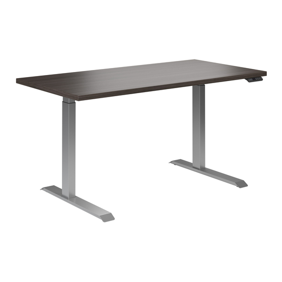
Ascent4 2-Leg Work Center
AS4LX-54-72-FXX-PS-X, AS4EX-54-72-FXX-PS-X
Parts Included
A
Leg
Qty: 2
B
Short Bracket
Qty: 2
C
Left End Bracket
Qty: 1
D
Right End Bracket
Qty: 1
E
Rear Motor
Bracket
Qty: 2
F
Connector Bracket
Qty: 1
Worksurface Required, Sold Separately:
Rectangles
Width
24" Feet
52–72"
30" Feet
52–72"
Offset Corners
Width
24" & 30" Feet
58–72"
30" Feet
58–72"
Workrite Ergonomics | 800.959.9675 www.workriteergo.com
G
4 mm Allen Wrench
Qty: 1
H
M6 × 14 mm Flat
Head Cap Screw
Qty: 16
I
#12 × ¾" Pan Head Screw
Qty: 31
J
M8 × 18 mm Flat
Head Cap Screw
Qty: 4
K
5 mm Allen Wrench
Qty: 1
L
Glide
Qty: 4
M
Control Box
Qty: 1
Depth
23–24"
29–30"
Offset
Depth
34–42"
23–24"
34–42"
29–30"
N
O
P
Q
R
S
STANDARD GLIDE
3RD LEG GLIDE
T
Tools Required:
#2 Phillips Bit
Cordless Drill
Screwdriver or
Driver/Drill
⅛" pilot drill bit
Cable Spool
Qty: 2
#8 × ⅝" Pan Head Screw
Qty: 12
3/ 1 6" Cable Loops
Qty: 10
Motor Cable
Qty: 1
Power Cord
Qty: 1
Feet
Qty: 2
Programmable Switch
Qty: 1
#3 Phillips Bit
Screwdriver or
Driver/Drill
" pilot drill bit
⁄
3
32
pencil
1 of 11
Advertisement

Related Manuals for Workrite Ergonomics Ascent4 AS4LX-54-72-FXX-PS-X


Summary of Contents for Workrite Ergonomics Ascent4 AS4LX-54-72-FXX-PS-X
- Page 1 Screwdriver or Screwdriver or Driver/Drill Driver/Drill Offset Corners Width Offset Depth 24" & 30" Feet 58–72" 34–42" 23–24" ⅛" pilot drill bit " pilot drill bit ⁄ 30" Feet 58–72" 34–42" 29–30" pencil Workrite Ergonomics | 800.959.9675 www.workriteergo.com 1 of 11...
- Page 2 Figure C In some cases, the images in this instruction may not match the power cord supplied with your electrical furnishing based on your region. Plug type, blade size, and shape may change. 2 of 11 Workrite Ergonomics | 800.959.9675 www.workriteergo.com...
- Page 3 Caution! Only use the M6 × 14 mm Flat Head Cap Screw (H) for assembly. 61" 55" 70" Work Centers 49" 43" 64" Work Centers 58" Work Centers 52" Work Centers Workrite Ergonomics | 800.959.9675 www.workriteergo.com 3 of 11...
- Page 4 Right End Bracket Hardware at actual size M6 × 14 mm Flat Head Cap Screw Left End Bracket Caution! Only use the M6 × 14 mm Flat Head Cap Screw (H) for assembly. 4 of 11 Workrite Ergonomics | 800.959.9675 www.workriteergo.com...
- Page 5 4.2 Use a ⅛" drill bit to drill pilot holes at the four corner locations. We recommend marking your drill bit so you do not drill any more than ¾" deep into your top. Be careful not to drill through your top! >¾" front 6.5" Workrite Ergonomics | 800.959.9675 www.workriteergo.com 5 of 11...
- Page 6 Note: Right hand location shown—the Switch (T) can be located on the right or left side of the table as required. The Control Box will need to be reversed in step 5 for left hand Switch mounting. 6 of 11 Workrite Ergonomics | 800.959.9675 www.workriteergo.com...
- Page 7 Left leg. 6.2 For Left Switch—Plug the Left leg cable into the Control Box (M). Next—Follow steps 6.3 and 6.4 above Hardware at actual size #12 × ¾" Pan Head Screw Workrite Ergonomics | 800.959.9675 www.workriteergo.com 7 of 11...
- Page 8 7.5 Secure the motor cable neatly to the top with up to 3 Cable Loops (P) and one (1) #8 × 5/ 8 " Pan Head Screw (O) per Cable Loop as required. Hardware at actual size Hardware at actual size #12 × ¾" Pan Head Screw #8 × ⅝" Pan Head Screw 8 of 11 Workrite Ergonomics | 800.959.9675 www.workriteergo.com...
- Page 9 #8 × 5/ 8 " Pan Head Screw (O) per Cable Loop as required. 8.4 Plug the Power Cord (R) into the Control Box (M). Hardware at actual size #8 × ⅝" Pan Head Screw Workrite Ergonomics | 800.959.9675 www.workriteergo.com 9 of 11...
-
Page 10: Cleaning Instructions
Do not use solvents and do not saturate or spray cleaners directly onto work center base. Programmable Switch Digital Readout Down Save Memory 1 Memory 2 Memory 3 Button Button Button Button 10 of 11 Workrite Ergonomics | 800.959.9675 www.workriteergo.com... - Page 11 Once unlocked the display will no longer read “LOC” and the digital display returns to normal. Workrite Ergonomics | 800.959.9675 www.workriteergo.com 11 of 11 #1500575 Rev B...
Need help?
Do you have a question about the Ascent4 AS4LX-54-72-FXX-PS-X and is the answer not in the manual?
Questions and answers