Table of Contents
Advertisement
Quick Links
Advertisement
Table of Contents
Troubleshooting

Related Manuals for ETAS ES420.1


Summary of Contents for ETAS ES420.1
- Page 1 ES420.1 Thermo Module User’s Guide...
- Page 2 The data in this document may not be altered or amended without special noti- fication from ETAS GmbH. ETAS GmbH undertakes no further obligation in rela- tion to this document. The software described in it can only be used if the customer is in possession of a general license agreement or single license.
-
Page 3: Table Of Contents
Features of the ES420.1 ........ -
Page 4: Fig. 5-17 Es400 Modules With Additional Etas Modules And Drive Recorder
General ..........53 5.4.2 ES420.1 with additional ETAS Modules (MC Application)..53 5.4.3 ES420.1 with additional ETAS Modules (Rapid Prototyping Application) - Page 5 LED Displays ..........63 Troubleshooting ES420.1 Problems ....... 64 Problems and Solutions .
- Page 6 10 ETAS Contact Addresses ........
-
Page 7: About This Manual
(serious) injury, if not avoided. CAUTION! identifies a hazard with low risk that could result in minor or medium physical injuries or property damages if not avoided. ES420.1 - User’s Guide... -
Page 8: Presentation Of Information
(see chapter 9.1 on page 115). Additional cables and adapters can be obtained separately from ETAS. A list of available accessories and their order designation is located in chapter "Accesso- ries" on page 116 of this manual or in the ETAS product catalog. -
Page 9: Basic Safety Notices
• "Requirements for Users and Duties for Operators" on page 9 • "Intended uUe" on page 9. General Safety Information Please observe the Product Safety Notices ("ETAS Safety Notice") and the follow- ing safety notices to avoid health issues or damage to the device. Note Carefully read the documentation (Product Safety Advice and this User's Guide) that belongs to the product prior to the startup. - Page 10 Connect the power cable only with a suitable vehicle battery or with a suitable lab power supply! The connection to power outlets is not allowed! To prevent an inadvertent insertion in power outlets, ETAS recom- mends to equip the power cables with safety banana plugs in areas with power outlets.
- Page 11 • Use exclusively ETAS cables at the connections of the module! • Adhere to the maximum permissible cable lengths! • Do not use any damaged cables! Cables may be repaired only by ETAS! CAUTION! Never apply force to insert a plug into a socket.
- Page 12 Please observe which way the module is pointing when installing ver- tically! Transport • Mount and connect the modules only at the location of their startup! • Do not transport the modules at the cable of the module or any other cables. ES420.1 - User’s Guide...
- Page 13 Maintenance The product is maintenance-free. Repair If a repair of an ETAS hardware product should become necessary, send the prod- uct to ETAS. Cleaning the module housing • Use a dry or lightly moistened, soft, lint-free cloth for cleaning the module housing.
- Page 14 Basic Safety Notices ETAS ES420.1 - User’s Guide...
-
Page 15: Es400 Product Family
Fig. 3-1 Central and Decentral Sensor Cabling With the ES400 modules, ETAS provides a decentral solution which considerably simplifies the test setup of the sensors. The basic idea of this concept is to install the modules of the ES400 family as close as possible to the sensors, to concatenate the modules with each other and to connect just the first module of this chain with the laptop in the vehicle. -
Page 16: Features Of The Es400 Line
• Each module has an LED for localizing the module. • The Thermo Modules of the ES400 family use a XCP-based protocol which is compatible to the existing ETAS Ethernet topology. The concept fulfils the following requirements: – High bandwidth to be able to realize lots of channels with high resolu-... -
Page 17: Housing
Data" on page 75. Housing A sturdy metal housing is used for the ES420.1; it has ports on the front of the device so it can fit into tight spaces. The ES420.1 is specifically designed to be installed in engine compartment, but also in the passenger cell. -
Page 18: Ports
Front 3.4.1 “Sensor” Port The front of the ES420.1 features a 22-pin Souriau port to which four sensors can be connected using a adapter cable. An individual sensor power supply port is available for each sensor. The use of a “cable tail” or “whip” solution with just one connector makes it possible to change the modules quickly within complex test setups. -
Page 19: Indicator
600 ms off 3.5.3 Functional State Display Functional State Note Yellow-red, flash- Warning Overload on a sensor supply ing, voltage channel semi bright, 1 Hz Red, Error state Error during self-test fully bright Red, Internal error semi bright ES420.1 - User’s Guide... - Page 20 ES400 Product Family ETAS ES420.1 - User’s Guide...
-
Page 21: Hardware Description
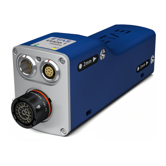
Features of the ES420.1 Fig. 4-1 ES420.1 Housing The ES420.1 Thermo Module is a member of the family of ES400 Modules. The ES420.1 can acquire temperatures at eight input channels. Overview of the major features of the ES420.1: • 8 galvanically isolated measurement channels for thermocouples •... -
Page 22: Block Diagram
Fig. 4-2 Block Diagram The ES420.1 is a module with eight identical sensor channels with common Cold Junction Compensation, two shared Ethernet interfaces and a power supply. Sensor Channels All sensor channels of the ES420.1 are identical. The thermocouple cold junction channels have a resolution of 24 bits. -
Page 23: Measurement Accuracy
ETAS Hardware Description The combination of thermocouple cold junction, replaceable splitter cable and ES420.1 enables temperatures to be measured highly precisely and virtually inde- pendently of environmental influences. Measurement Accuracy While measuring temperatures with thermocouples the total measurement inac- curacy is determined by different parts. These parts are: •... - Page 24 T = 2.27 K In this example the maximum total inaccuracy is determined by the inaccuracy of the cold junction compensation and the part of the inaccuracy that depends on the internal resistance of the thermocouple. ES420.1 - User’s Guide...
-
Page 25: Data Transfer
Message Format “XCP on UDP” (Schematic) Using the UDP/IP standard for data transfer makes it possible to connect the modules directly to a PC, a router or a switch. In XCP communication, the PC has the master function. ES420.1 - User’s Guide... -
Page 26: Realization
The communication protocol used by the ES400 family makes it possible for third-party suppliers to use the communication protocol for their own, non- ETAS applications once the modules have been configured with the „ES4xx Configuration Tool from ES4xx_DRV_SW“ . 4.5.2... - Page 27 IEEE1588 (Precision Time Protocol). The modules add the time stamp to the Ethernet data package for every measure date. The combination of time stamp synchronization, full duplex and time slice proce- dure results in a very high reference data rate of the modules. ES420.1 - User’s Guide...
-
Page 28: Examples
4.5.3 Examples Example 1 Fig. 4-4 on page 28 shows an example of an application with three concatenated ES400 modules with the same acquisition rates. The transfer scheme for this configuration is shown in Fig. 4-5 on page 28. M ODUL 1 M ODUL 2 M ODUL 3 St ellgrößen... -
Page 29: Fig. 4-7 Transfer Scheme For Example 2 (Simplified, Not True To Scale)
Example 2 Fig. 4-6 on page 29 shows an example in which three modules with different acquisition rates are linked to each other. The transfer scheme for this configuration is shown in Fig. 4-7 on page 29. M ODUL 1 M ODUL 2 M ODUL 3 St ellgrößen... - Page 30 ETAS ES420.1 - User’s Guide...
-
Page 31: Power Supply
ES400 modules with supply voltages between 5 V and 50 V DC over the entire temperature range. With the power supply management of the ES420.1, you can use an automatic power-saving feature (“Standby”) as well as a “Wake Up” function via the Ether- net interface. - Page 32 ETAS Example 1: For module chains which are equipped exclusively with ES420.1 modules, ETAS recommends the use of Y boost cables if the length of the mod- ule chain • is longer than 8 modules (without sensor feeding) or • is longer than 5 modules (with sensor feeding).
-
Page 33: Configuration
ETAS Configuration The configuration of the ES420.1 is performed entirely via the GUI within INCA. The configuration of the individual channels is saved either in INCA or in the individual ES400 modules. In the first case, you can prepare settings for specific measure tasks, e.g. - Page 34 ETAS ES420.1 - User’s Guide...
-
Page 35: Getting Started
CAUTION! Potential equalization in the vehicle over the shield of the Ethernet connecting cables of modules may occur! Mount the modules only to components with the same electrical potential or insulate the modules from the components. ES420.1 - User’s Guide... -
Page 36: Guarantee Of Features As Defined By Ip67
Fig. 5-1 Position of the Pressure Balance Element Standing liquids or liquids which do not flow away from the pressure balance element can permanently damage the membrane. The module then loses the features defined by IP67. ES420.1 - User’s Guide... -
Page 37: Assembly
(see Fig. 5-3 on page 37) on the right-hand side of the mod- ule. Fig. 5-4 Unscrewed Integrated Assembly Elements Openings for Cable Fasteners Every module base has two openings each on the right and left-hand side for attaching the modules to other components using cable fasteners. ES420.1 - User’s Guide... - Page 38 – on DIN rails with ES4xx angle brackets (right) or – on other components, • Attaching ES400 modules with cable fasteners: – on DIN rails with ES4xx angle brackets (left) or – on DIN rails with ES4xx angle brackets (right) or – on other components. ES420.1 - User’s Guide...
-
Page 39: Connecting Several Es400 Modules Mechanically
• Position the modules so that their fronts are in a line. • Hold the two modules together firmly on their outer sides. Connecting the Modules To connect several ES400 modules, you require a 2 mm Allen key (minimum length 20 mm). ES420.1 - User’s Guide... - Page 40 To connect the ES400 module to other modules, you require a 2 mm Allen key (minimum length 20 mm). To connect to other modules: • Assemble other modules in accordance with the procedure described in the section 5.2.2 on page 39 . ES420.1 - User’s Guide...
-
Page 41: Attaching Es400 Modules To Other Components Using The Integrated
The threads should be cut 8 mm deep. Note Use the drilling template. Connecting the Module to the Component To connect the ES400 module to the component, you require a 2 mm Allen key (minimum length 20 mm). ES420.1 - User’s Guide... - Page 42 To connect the ES400 module to other modules, you require a 2 mm Allen key (minimum length 20 mm). To connect to other modules: • Assemble other modules in accordance with the procedure described in the section 5.2.2 on page 39 . ES420.1 - User’s Guide...
-
Page 43: Fig. 5-8 Connecting To Other Modules
ETAS Getting Started Fig. 5-8 Connecting to other modules ES420.1 - User’s Guide... -
Page 44: Attaching Es400 Modules On Din Rails With The Integrated Assembly Elements
2 mm hex key (minimum length 20 mm). Connecting the module and the ES4xx Angle Bracket (left): • Position the module to the right of the ES4xx angle bracket (left). • Align the integrated assembly elements of the mod- ule with the bores. ES420.1 - User’s Guide... - Page 45 DIN rail. • Engage the ES4xx angle bracket in the DIN rail by pressing on the ES4xx angle bracket or the module. • The module connected with the ES4xx angle bracket is fastened to the DIN rail. ES420.1 - User’s Guide...
-
Page 46: Attaching Es400 Modules To Other Components With Screws
Use the drilling template to prepare the component (see Fig. 5-13 on page 51). Connecting the Module to the Component To connect the ES400 module to the component, you need two screws M3 and a screwdriver. ES420.1 - User’s Guide... - Page 47 (see section 5.2.2 on page 39). The module on the extreme right of the module block is connected to the other component like an individual module - using screws. ES420.1 - User’s Guide...
-
Page 48: Attaching Es400 Modules On Din Rails Using Screws
The pin of the integrated assembly element can be screwed out of the module by approximately 6 mm. Connecting the Module with the ES4xx Angle Bracket (right) To connect the ES400 module with the ES4xx angle bracket (right) requires two M3 screws, two washers and a screwdriver. ES420.1 - User’s Guide... - Page 49 Connecting the ES4xx Angle Bracket (right) with the DIN rail • Place the ES4xx angle bracket onto the DIN rail. • Insert the hooks of the ES4xx angle bracket into the upper part of the DIN rail. ES420.1 - User’s Guide...
-
Page 50: Attaching Es400 Modules To Other Components Using Cable Fasten
DIN rail. • Engage the ES4xx angle bracket in the DIN rail by pressing on the ES4xx angle bracket or the module. • The module connected with the ES4xx angle bracket is fastened to the DIN rail. ES420.1 - User’s Guide... -
Page 51: Drilling Template
ETAS Getting Started Drilling Template Fig. 5-13 Drilling Template ES420.1 - User’s Guide... - Page 52 Getting Started ETAS ES420.1 - User’s Guide...
-
Page 53: Applications
ES420.1 with additional ETAS Modules for MC Applications The ETAS Daisy Chain concept enables a simple network architecture since only the ES420.1 or the first module of the module chain is connected with the PC or with the "ETH" port of the ES59x.1. -
Page 54: Es420.1 With Additional Etas Modules (Rapid Prototyping Application)
1 Type per Module Vehicle, Test Bench, Motor, ... Fig. 5-15 ES420.1 with ES910.3 and additional ETAS Modules for Rapid Proto- typing Applications The concept of the ES4xx/ES63x/ES93x product family to install the modules as close as possible to the sensors, the chain the modules with each other, and to connect only the first module of this chain with the ES910.3 or the RTPRO-PC,... -
Page 55: Wiring Examples
ETAS Wiring Examples 5.5.1 ES400 Modules with additional ETAS Modules (Measurement and Calibration) Power Supply Daisy Chain Modules Power Supply ES595 ES411/ ES415 Fig. 5-16 ES400 Modules with additional ETAS Modules (Measurement and Calibration) Cable in Function Order name Fig. 5-16... -
Page 56: Es400 Modules With Additional Etas Modules And Drive Recorder (Measurement And Calibration)
ETAS 5.5.2 ES400 Modules with additional ETAS Modules and Drive Recorder (Measurement and Calibration) Vehicle Drive Recorder 10/100 MBit/s Ethernet Power Supply Daisy Chain Modules Daisy Chain Measurement Modules ES411/ ES59x ES415 Lambda Ambient / Voltage Sensor Tempera- Frequency, Exhaust... -
Page 57: Es400 Modules With Es910.3 (Rapid Prototyping)
Power supply and Ethernet cable Daisy Chain CBEP430, modules CBEP4305 ETK connection cable CBM150 5, 6 CAN/LIN/FLX connection cable (CAN/LIN/FLX CBCFI100 combined) at ES910.3, at ES921.1 CAN connection cable (CAN only), at ES910.3, CBAC130, at ES921.1 CBAC140, CBAC150, CBCX130 ES420.1 - User’s Guide... -
Page 58: Es400 Modules With Es910.3 And Drive Recorder (Rapid Prototyping)
Function Order name Fig. 5-19 Ethernet adapter cable (100 Mbit/s) CBAE330 (con- nected to cable 2) Ethernet connection cable(1 Gbit/s) CBE230 (con- nected to cable 1) Power supply and Ethernet cable Daisy Chain CBEP430, modules CBEP4305 ES420.1 - User’s Guide... -
Page 59: Es400 Modules With Etas Rtpro-Pc (Rapid Prototyping)
ETAS 5.5.5 ES400 Modules with ETAS RTPRO-PC (Rapid Prototyping) Ethernet USB2 Power Supply Daisy Chain Modules ES581.3 ES411/ ES415 Fig. 5-20 ES400 Modules with ETAS RTPRO-PC (Rapid Prototyping) Cable in Function Order name Fig. 5-20 Power supply and Ethernet cable PC and Daisy... - Page 60 ETAS ES420.1 - User’s Guide...
-
Page 61: Wiring
An overview is contained in the chapter 8 on page 89. 5.6.1 “Sensor” Port You can use different cables to connect the sensors to the ES420.1: • CBATx400.1-x sensor cable If you have used thermo elements with mini connectors in your test set- up, this adapter cable allows you to continue to use the wiring you have used to date for your test set-up. - Page 62 • Connect the combined Ethernet and power supply cable to the “OUT” port of the ES420.1 of the last module of the chain towards the PC. • Connect the combined Ethernet and power supply cable to the “IN”...
-
Page 63: Troubleshooting Problems
Please observe the LEDs which provide information on the functions of the inter- face and the ES420.1 (see the chapter "Indicator" on page 19) to be able to judge the operational state of the ES420.1 as well as troubleshooting measures. -
Page 64: Troubleshooting Es420.1 Problems
4.6 on page 31. Is the hardware connected Check that the wiring is to the PC? undamaged. Are the modules in the Check that the wiring is module chain connected undamaged. correctly? ES420.1 - User’s Guide... - Page 65 ETAS network. Wire your test setup (ETAS modules and their connec- tion to the PC) with ETAS cables only. Are you using the correct Check whether you are type of network card in using a PCMCIA network your laptop? card in your laptop.
- Page 66 Reload the measure con- figuration. If the LED continues to show red, send the mod- ule to ETAS for repair. The firmware of one or Is the module to be Update the firmware of more modules cannot...
-
Page 67: Problems And Solutions
Windows 2000 and XP systems. Network security policies, however, may request the APIPA mechanism to be disabled. In this case, you cannot use a network adapter which is configured for DHCP to access ETAS hardware. The ETAS Net- work Manager displays a warning message. - Page 68 If you use more than one PC or notebook for accessing the same ETAS hardware, the network adapters used must be configured to use the same logical network. If this is not possible, it is necessary to switch the ETAS hardware off and on again between different sessions (repowering).
- Page 69 It is possible after a certain period of time without data traffic that the network card automatically interrupts the Ethernet connection. This can be prevented by setting the registry key autodisconnect. Setting the Registry Key autodisconnect: • Open the Registry Editor. ES420.1 - User’s Guide...
-
Page 70: Personal Firewall Blocks Communication
Ethernet hardware at all, although the configuration parameters are correct. Some actions in ETAS products can lead to problems if the firewall is not properly parameterized, e.g. when opening the experiment environment in ASCET or for the hardware search by INCA or HSP. - Page 71 The firewall no longer blocks the ETAS product (here: ASCET). The setting is retained after a restart of the product or the PC. Instead of waiting for the "Windows Security Warning", you can enable ETAS products in advance. Enabling ETAS products in the firewall control: •...
- Page 72 This tab lists the exceptions that are not blocked by the firewall. Use the button Program or Edit to add new programs or to edit existing ones. • Ensure that the ETAS products and services to be used are correctly configured exceptions. ES420.1 - User’s Guide...
- Page 73 A correct operation of the product is not possible since the database file as well as various *.ini files are modified during the work. The ETAS software must be installed by an administrator in any case. It is recom- mended that the administrator ensure that the ETAS product or the processes are added to the list of selected exceptions of the Windows Firewall after the instal- lation.
- Page 74 • Close the window with OK. An administrator must select the product on the "Exceptions" tab of the "Windows Firewall" win- dow to avoid future problems during the hardware access with the corresponding ETAS product. ES420.1 - User’s Guide...
-
Page 75: Technical Data
Connection of sensor cable SN: 1234567 Serial number (seven-digit) Vx.y.z Hardware version of the product F 00K 123 456 Ordering number of the product, see chapter 9.1 on page 115 Operating voltage range (DC), Power consumption ES420.1 - User’s Guide... -
Page 76: Standards And Norms
In addition, the combination was tested by cascaded modules. ISO 16750-3, Sec. 4.2.2.2 Mech. shock 3 space axis, half sinus, Acceleration: 500 m/s², Shock duration: 6 ms, Shocks per direction and axis: 10, Units under test: active ES420.1 - User’s Guide... - Page 77 DIN 5596-1 Stone impact IPX7 Protection class test: Protection class IP67 EN61000-4-2 Immunity ESD EN61000-4-3 Immunity radiated RF EN61000-4-4 Immunity EFT/B EN61000-4-5 Immunity surge EN61000-4-6 Immunity conducted RF DIN EN 55022 B Emission radiation/ radio interference voltage ES420.1 - User’s Guide...
-
Page 78: Environmental Conditions
7.1.4 Maintenance the Product Do not open or change the module! Works on the module housing may be exe- cuted only by qualified technical personnel. Send defect modules to ETAS. 7.1.5 Cleaning the product We recommend to clean the product with a dry cloth. -
Page 79: Rohs Conformity
The user is obligated to separate the waste equipment and to provide it to the WEEE return system for reuse. The WEEE Directive applies to all ETAS devices, but not to external cables or bat- teries. Additional information about the recycling program of ETAS GmbH is available from the ETAS sales and service locations (see chapter 10 on page 119). -
Page 80: Declarable Substances
Some products from ETAS GmbH (e.g. modules, boards, cables) use components with substances that are subject to declaration in accordance with the REACH regulation (EU) no.1907/2006. Detailed information is located in the ETAS download center in the customer information "REACH Declaration" (www.etas.com/Reach). This information is continuously being updated. -
Page 81: Software
ETAS Technical Data 7.7.2 Software To configure the ES420.1 and for control and data acquisition, you need soft- ware in the following versions: • INCA V6.0 • ES4xx Configuration Tool V1.0.5 and higher from ES4xx_DRV_SW (stand- alone operation) • ES4xx driver LabVIEW Integration V1.0.0 and higher from ES4xx_DRV_SW •... -
Page 82: Electrical Data
• "Host Interface" on page 83 • "Sensor Inputs" on page 83. Note ETAS guarantees measurement accuracy of the ES420.1 for one year. Please use our calibration service (see section 4.10 on page 33)! Note Unless otherwise specified, all data applies at 25 °C. -
Page 83: Host Interface
±0.2 K/K for type B ±0.008 K/K for type E ±0.008 K/K for type J ±0.01 K/K for type K ±0.016 K/K for type N ±0.008 K/K for type R ±0.008 K/K for type S ±0.01 K/K for type T ES420.1 - User’s Guide... - Page 84 Maximum inaccuracy of cold junction ±0.4 K compensationT Maximum temperature drift of cold ±0.002 K/K junction compensation T Maximum input voltage 32 V DC for T , T and T Reference temperature T is 25 °C (equivalent to 298.15 K). ES420.1 - User’s Guide...
-
Page 85: Pin Assignment
• "“IN” Connector" on page 85 • "“OUT” Connector" on page 86 • "“Sensor” Connector" on page 87. Note All connectors are shown with a view of the front of the ES420.1. All shields are at case potential. 7.9.1 “IN” Connector Fig. -
Page 86: Out" Connector
ETAS 7.9.2 “OUT” Connector Fig. 7-3 “OUT” Connector Signal Meaning UBatt Operating voltage UBatt Operating voltage Ground Ground Received data, plus Send data, minus Received data, minus Ground Ground Send data, plus ES420.1 - User’s Guide... -
Page 87: Sensor" Connector
Sensor channel 4, input plus TEDS- TEDS, cable CH2 In- Sensor channel 2, input minus TEDS+ TEDS, cable CH7 In+ Sensor channel 7, input plus PT100M- Cold junction compensation CH5 In- Sensor channel 5, input minus PT100S+ Cold junction compensation ES420.1 - User’s Guide... - Page 88 ETAS ES420.1 - User’s Guide...
-
Page 89: Cables And Accessories
• "Cables for the connector "Sensor"" on page 107 • "Protective Caps" on page 111 • "Angle brackets" on page 113. Note Only use ETAS cables at the interfaces of the module. Adhere to the maximum cable lengths! ES420.1 - User’s Guide... - Page 90 Cables and Accessories ETAS ES420.1 - User’s Guide...
-
Page 91: Combined Ethernet And Power Supply Cable
The connection to power outlets is not allowed! To prevent an inadvertent insertion in power outlets, ETAS recom- mends to equip the combined ethernet and power supply cables with safety banana plugs in areas with power outlets. -
Page 92: Cbep410.1 Cable
(MINI flat automotive fuse, quick-response, 3 A, 58 V). Robust, waterproof and dust-proof (IP67). Temperature rated for: -40 °C to +125 °C/ -40 °F to +257 °F Product Length Order number CBEP410.1-3 F 00K 104 927 ES420.1 - User’s Guide... -
Page 93: Cbep4105.1 Cable
(MINI flat automotive fuse, quick-response, 3 A, 58 V). Robust, waterproof and dust-proof (IP67). Temperature rated for: -40 °C to +125 °C/ -40 °F to +257 °F Product Length Order number CBEP4105.1-3 F 00K 110 026 ES420.1 - User’s Guide... -
Page 94: Cbep415.1 Cable
(MINI flat automotive fuse, quick-response, 3 A, 58 V). Robust, waterproof and dust-proof (IP67). Temperature rated for: -40 °C to +125 °C/ -40 °F to +257 °F Product Length Order number CBEP415.1-5 F 00K 105 680 ES420.1 - User’s Guide... -
Page 95: Cbep4155.1 Cable
(MINI flat automotive fuse, quick-response, 3 A, 58 V). Robust, waterproof and dust-proof (IP67). Temperature rated for: -40 °C to +125 °C/ -40 °F to +257 °F Product Length Order number CBEP4155.1-5 F 00K 110 027 ES420.1 - User’s Guide... -
Page 96: Cbep420.1 Cable
(MINI flat automotive fuse, quick-response, 3 A, 58 V). Robust, waterproof and dust-proof (IP67). Temperature rated for: -40 °C to +125 °C/ -40 °F to +257 °F Product Length Order number CBEP420.1-3 F 00K 105 292 ES420.1 - User’s Guide... -
Page 97: Cbep4205.1 Cable
(MINI flat automotive fuse, quick-response, 3 A, 58 V). Robust, waterproof and dust-proof (IP67). Temperature rated for: -40 °C to +125 °C/ -40 °F to +257 °F Product Length Order number CBEP4205.1-3 F 00K 110 041 ES420.1 - User’s Guide... -
Page 98: Cbep425.1 Cable
(MINI flat automotive fuse, quick-response, 3 A, 58 V). Robust, waterproof and dust-proof (IP67). Temperature rated for: -40 °C to +125 °C/ -40 °F to +257 °F Product Length Order number CBEP425.1-3 F 00K 105 972 ES420.1 - User’s Guide... -
Page 99: Cbep4255.1 Cable
(MINI flat automotive fuse, quick-response, 3 A, 58 V). Robust, waterproof and dust-proof (IP67). Temperature rated for: -40 °C to +125 °C/ -40 °F to +257 °F Product Length Order number CBEP4255.1-3 F 00K 110 029 ES420.1 - User’s Guide... -
Page 100: Cbep430.1 Cable
(MINI flat automotive fuse, quick-response, 3 A, 58 V). Robust, waterproof and dust-proof (IP67). Temperature rated for: -40 °C to +125 °C/ -40 °F to +257 °F Product Length Order number CBEP430.1-0m5 0.5 m F 00K 104 928 ES420.1 - User’s Guide... -
Page 101: Cbep4305.1 Cable
(MINI flat automotive fuse, quick-response, 3 A, 58 V). Robust, waterproof and dust-proof (IP67). Temperature rated for: -40 °C to +125 °C/ -40 °F to +257 °F Product Length Order number CBEP4305.1-0m5 0.5 m F 00K 110 030 ES420.1 - User’s Guide... - Page 102 ETAS ES420.1 - User’s Guide...
-
Page 103: Ethernet Cable
This chapter contains information on the following cables: • "CBE400.2 Cable" on page 104 • "CBE401.1 Cable" on page 104 • "CBE430.1 Cable" on page 105 • "CBE431.1 Cable" on page 105 • "CBEX400.1 Cable" on page 106 • "ES4xx_BRIDGE" on page 106. ES420.1 - User’s Guide... -
Page 104: Cbe400.2 Cable
(MINI flat automotive fuse, quick-response, 3 A, 58 V). Robust, waterproof and dust-proof (IP67). Temperature rated for: -40 °C to +125 °C/ -40 °F to +257 °F Product Length Order number CBE401.1-0m5 0.5 m F 00K 106 128 ES420.1 - User’s Guide... -
Page 105: Cbe430.1 Cable
Robust, waterproof and dust-proof (IP67). Temperature rated for: -40 °C to +125 °C/ -40 °F to +257 °F Product Length Order number CBE431.1-0m14 0.14 m F 00K 105 676 CBE431.1-0m30 0.30 m F 00K 105 685 ES420.1 - User’s Guide... -
Page 106: Cbex400.1 Cable
Product Length Order number CBEX400.1-3 F 00K 105 294 8.2.6 ES4xx_BRIDGE Fig. 8-16 ES4xx Bridge Ethernet bridge connecting blocked ES400 modules. Facilitates very compact measurement setups. IP67 compliant. Product Order number ES4xx_BRIDGE F 00K 105 684 ES420.1 - User’s Guide... -
Page 107: Cables For The Connector "Sensor
CBATx401.x Cable The CBATx401.x cable consists of eight identical cable sections, marked n=1 to n=8. Each cable section is assigned to an ES420.1 measurement channel and wired according to the same scheme. The assignment of the cable connectors of a cable section to the signals of a measurement channel is shown in the table. -
Page 108: As_Cbatk401.1-1 Cable
AS_CBATK401.1 Cable The AS_CBATK401.1 cable consists of eight identical cable sections, marked n=1 to n=8. Each cable section is assigned to an ES420.1 measurement channel and wired according to the same scheme. The assignment of the cable connectors of a cable section to the signals of a measurement channel is shown in the table. -
Page 109: As_Cbatk402.1-1 Cable
AS_CBATK402.1 Cable The AS_CBATK402.1 cable consists of eight identical cable sections, marked n=1 to n=8. Each cable section is assigned to an ES420.1 measurement channel and wired according to the same scheme. The assignment of the cable connectors of a cable section to the signals of a measurement channel is shown in the table. - Page 110 ETAS ES420.1 - User’s Guide...
-
Page 111: Protective Caps
ETAS Protective Caps The connections "IN" and "OUT" of the ES420.1 can be protected with different protective caps according to the operating conditions. 8.4.1 Protective Caps supplied The "IN" and "OUT" ports of the ES4xx are covered with simple dust and trans- port caps on delivery. -
Page 112: Cap Cap_Souriau_8Sta
ETAS 8.4.4 Cap CAP_SOURIAU_8STA Fig. 8-22 Cap CAP_SOURIAU_8STA The cap CAP_SOURIAU_8STA protects the "Sensor" port against water and dirt. Product Order number CAP_SOURIAU_8STA F 00K 105 303 ES420.1 - User’s Guide... -
Page 113: Angle Brackets
Angle Bracket for mounting ES4xx modules to a DIN rail 35 x 7.5 (EN 60715 TH35). Stainless steel V2A. For mounting on right side of an ES4xx module. Product Order number Angle bracket right F 00K 107 176 ES420.1 - User’s Guide... - Page 114 ETAS ES420.1 - User’s Guide...
-
Page 115: Ordering Information
Order number ES420.1 Thermo Module (8-CH) ES420.1 F 00K 104 403 Scope of supply ES420.1 Micro Thermo Measurement Mod- ule (8 channels, for universal thermocouple splitter cable), CDROM ES4xx_DRV_SW_CD (drivers for ES4xx and documentation), List "Content of this Package“, ES4xx Safety... -
Page 116: Accessories
Ordering Information ETAS Accessories 9.3.1 Cables Note If you require customized cables, please contact your ETAS contact partner or sales.de@etas.com. Cables for the connectors "IN" and "OUT" Ethernet cable: Order name Short name Order number Ethernet Chain Connection Cable, Lemo 1B CBE400.2-3... - Page 117 F 00K 110 030 ply Cable, Lemo 1B FGL - Lemo 1B FGA - Safety Banana (8fc-8mc-2mc), 0m5 Ethernet Bridge: Order name Short name Order number Bridge to connect two assembled ES4xx_BRIDGE F 00K 105 684 ES4xx Modules ES420.1 - User’s Guide...
-
Page 118: Protective Caps
ES4xx Angle Bracket left ES4xx_AB_L F 00K 107 175 ES4xx Angle Bracket right ES4xx_AB_R F 00K 107 176 9.3.4 Device Calibration Order name Short name Order number Calibration Service for ES420.1 K_ES420 F 00K 105 297 ES420.1 - User’s Guide... -
Page 119: Etas Contact Addresses
Germany WWW: www.etas.com ETAS Subsidiaries and Technical Support For details of your local sales office as well as your local technical support team and product hotlines, take a look at the ETAS website: ETAS subsidiaries WWW: www.etas.com/en/contact.php ETAS technical support WWW: www.etas.com/en/hotlines.php... - Page 120 ETAS Contact Addresses ETAS ES420.1 - User’s Guide...
-
Page 121: Figures
Openings for Cable Fasteners in ES400 Modules......... 50 Fig. 5-13 Drilling Template ..................51 Fig. 5-14 ES420.1 with additional ETAS Modules for MC Applications ....... 53 Fig. 5-15 ES420.1 with ES910.3 and additional ETAS Modules for Rapid Prototyping Applications....................54... - Page 122 Figures ETAS Fig. 5-16 ES400 Modules with additional ETAS Modules (Measurement and Calibration) Fig. 5-17 ES400 Modules with additional ETAS Modules and Drive Recorder (Measure- ment and Calibration)................. 56 Fig. 5-18 ES400 Modules with ES910.3 (Rapid Prototyping)........57 Fig. 5-19 ES400 Modules with ES910.3 and Drive Recorder (Rapid Prototyping)..
-
Page 123: Index
CBE401.1 104 mechanical 78 CBE430.1 105 Data transfer 25 CBE431.1 105 Decentral wiring concept 16 CBEP410.1 92 Device calibration 118 CBEP4105.1 93 Documentation 9 CBEP415.1 94 Drilling template 51 CBEP4155.1 95 Duplex operation 25 CBEP420.1 96 ES420.1 - User’s Guide... - Page 124 Synchronization of the timebases 27 Synchronization, clock generator 27 Openings for cable fasteners 37 Operation Temperature drift 83 Conventions 8 Time slice procedure 26 Use Case 8 Time stamp 25 Operational state 19 Tool integration 33 Ordering 115 Troubleshooting 64 ES420.1 - User’s Guide...
- Page 125 Waste Electrical and Electronic Equip- ment - WEEE 79 Water 36 WEEE return system 79 Wiring 61 Wiring concepts 15 Wiring, Daisy Chain 61 Wiring, sensors 61 XCP 16 XCP protocol 25 Y boost cable 31 ES420.1 - User’s Guide...
- Page 126 Index ETAS ES420.1 - User’s Guide...
Need help?
Do you have a question about the ES420.1 and is the answer not in the manual?
Questions and answers