Table of Contents
Advertisement
Quick Links
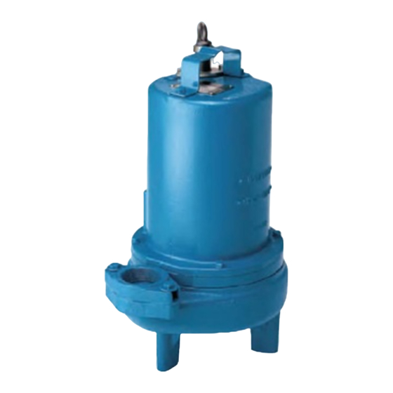
INSTALLATION and OPERATION MANUAL
Submersible Fountain Pumps
IMPORTANT!
Read all instructions in this manual before operating pump.
As a result of Crane Pumps & Systems, Inc., constant product improvement program,
product changes may occur. As such Crane Pumps & Systems reserves the right to
change product without prior written notifi cation.
A Crane Co. Company
420 Third Street
Piqua, Ohio 45356
Phone: (937) 778-8947
Fax: (937) 773-7157
www.cranepumps.com
Manual Index
BARNES
BARNES
Series: SF & 3SF-L
.5 & 1.0 HP,
1750 RPM, 60 Hz.
83 West Drive, Bramton
Ontario, Canada L6T 2J6
Phone: (905) 457-6223
Fax: (905) 457-2650
®
Form No. 109999-Rev. T
Advertisement
Table of Contents

Related Manuals for Barnes SF Series


Summary of Contents for Barnes SF Series
- Page 1 Manual Index BARNES BARNES ® INSTALLATION and OPERATION MANUAL Submersible Fountain Pumps Series: SF & 3SF-L .5 & 1.0 HP, 1750 RPM, 60 Hz. IMPORTANT! Read all instructions in this manual before operating pump. As a result of Crane Pumps & Systems, Inc., constant product improvement program, product changes may occur.
-
Page 2: Table Of Contents
PRESSURE GAUGE KIT (see parts list) Other brand and product names are trademarks or registered trademarks of their respective holders. ® Barnes is a registered trademark of Crane Pumps & Systems, Inc 2000, 2002, 5/04, 9/05, 5/06, 9/06 Alteration Rights Reserved... -
Page 3: Safety First
SAFETY FIRST! Please Read This Before Installing Or Operating Pump. This information is provided for SAFETY and to PREVENT Do not block or restrict discharge hose, as discharge EQUIPMENT PROBLEMS. To help recognize this information, hose may whip under pressure. observe the following symbols: IMPORTANT! Warns about hazards that can result WARNING! - DO NOT wear loose clothing that may... -
Page 4: Pump Specifications
SECTION: A - PUMP SPECIFICATIONS: DISCHARGE ....2” NPT, Vertical, Bolt-on Flange UPPER BEARING: LIQUID TEMP ....104°F (40°C) Intermittent Design ..Single Row, Ball, Oil Lubricated MOTOR HOUSING ..Cast Iron ASTM A-48, Class 30 Load ..... Radial VOLUTE ......Cast Iron ASTM A-48, Class 30 LOWER BEARING: SEAL PLATE .... - Page 5 SECTION: A - PUMP SPECIFICATIONS: DISCHARGE ....3” NPT, Vertical, Bolt-on Flange UPPER BEARING: LIQUID TEMP ....104°F (40°C) Intermittent Design ..Single Row, Ball, Oil Lubricated MOTOR HOUSING ..Cast Iron ASTM A-48, Class 30 Load ..... Radial VOLUTE ......Cast Iron ASTM A-48, Class 30 LOWER BEARING: SEAL PLATE ....
-
Page 6: General Information
B-4) Service Centers: For the location of the nearest Barnes Service Center, check your Barnes representative or Crane Pumps & Systems, Inc., Service Department in Piqua, Ohio, telephone (937) 778-8947 or Crane Pumps &... -
Page 7: Electrical Data
General Comments: 1) Never work in the sump with the power on. C-4) Electrical Connections: An acceptable motor control switch shall be provided at the 2) Level controls are factory set for a pumping differential time of installation. of 9 inches. If that is the cycle desired, simply circle the discharge pipe with the pipe mounting strap, feed C-4.1) Power Cords: the end through the worm drive, and tighten with a... -
Page 8: Start-Up Operation
Return one copy to 3.) If oil is found to be clean and uncontaminated Barnes Pumps, Inc. and store a copy in the control panel or (measuring above 15 KV. breakdown), refi ll the motor with the pump manual if no control panel is used. - Page 9 Pressurize motor housing to 10 P.S.I. Use soap solution around the sealed areas and inspect joints for “air bubbles”. If, after fi ve minutes, the pressure is still holding constant, and no “bubbles” are observed, slowly bleed the pressure and remove the gauge assembly. Replace oil as described in section F-1.4.
- Page 10 Make sure the stationary member is in straight. Slide a bullet (see parts list - seal tool kit) over motor shaft. Lightly oil (DO NOT use grease) shaft, bullet and inner surface of bellows on rotating member (28b), see Figure 9. With lapped surface of rotating member (28b) facing inward toward stationary member, slide rotating member over bullet and onto shaft, using seal pusher, Motor &...
- Page 11 underside of the terminal block (21), see Figure 10. The unit voltage should be noted. Remove socket head capscrew (47). Vertically lift the motor housing (6) from seal plate (5) by lifting handle (13). Inspect square ring (27) Power Cord (16) for damage or cuts.
-
Page 12: Replacement Parts
terminal block (21) into the housing so it seats completely below the snap ring groove. Place snap ring (19) into groove in cord entry bore of housing. F-4.4) Cord Assemblies: Power Cord - Refi ll the cooling oil as outlined in paragraph F-1.3. -
Page 13: Trouble Shooting
TROUBLE SHOOTING CAUTION ! Always disconnect the pump from the electrical power source before handling. If the system fails to operate properly, carefully read instructions and perform maintenance recommendations. If operating problems persist, the following chart may be of assistance in identifying and correcting them: MATCH “CAUSE”... -
Page 14: Cross-Section (Fig. 15)
FIGURE 15... -
Page 15: Exploded View (Fig. 16)
FIGURE 16... -
Page 16: Parts List
PARTS KITS Seal Repair Kits ....P/N - 107272 (†) 2, 27, 28, 36 Seal Tool Kit ....P/N - 107271 Pressure Gauge Kit ..P/N - 085343 PARTS LIST ITEM QTY. PART NO. DESCRIPTION 055400 Volute 069140 Gasket 026210 Flange 2” Discharge 105153 3”... - Page 17 069140 Gasket 014270 Pipe Plug .375” NPT 1-36-1 Hex. Hd. Cap Screw 2” Discharge, 3/8-16 x 1.25” Lg., Stainless 1-131-1 Hex. Hd. Cap Screw 3” Discharge, 5/16-18 x 1.25” Lg., Stainless ----- Loctite 242 ----- Permatex 2C 082727 Washer 2” Discharge, 3/8” Stainless 084948 Socket Head Cap Screw 1/4-20 x 1.25”...
-
Page 19: Warranty
IMPORTANT! WARRANTY REGISTRATION Your product is covered by the enclosed Warranty. To complete the Warranty Registration Form go to: http://www.cranepumps.com/ProductRegistration/ If you have a claim under the provision of the warranty, contact your local Crane Pumps & Systems, Inc. Distributor. RETURNED GOODS RETURN OF MERCHANDISE REQUIRES A “RETURNED GOODS AUTHORIZATION”. - Page 20 Notes...