Table of Contents
Advertisement
INSTALLATION and OPERATION MANUAL
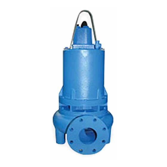
Submersible Non-Clog Pump
IMPORTANT!
Read all instructions in this manual before operating pump.
As a result of Crane Pumps & Systems, Inc., constant product improvement program,
product changes may occur. As such Crane Pumps & Systems reserves the right to
change product without prior written notifi cation.
A Crane Co. Company
420 Third Street
Piqua, Ohio 45356
Phone: (937) 778-8947
Fax: (937) 773-7157
www.cranepumps.com
Manual Index
BARNES
83 West Drive, Bramton
Ontario, Canada L6T 2J6
Phone: (905) 457-6223
Fax: (905) 457-2650
®
Series:
4SE-L, 4.5 - 11.3HP
1150RPM, 60Hz
Series:
4SE-L, 4.5 - 15HP
1750RPM, 60Hz
Series:
4SEU-L, 15HP
1750 & 3450RPM,
60Hz
Series:
4SE-HL, 4.5 - 7.5HP
1150RPM, 60Hz
Series:
4SE-HL, 7.5 - 15HP
1750RPM, 60Hz
Series:
4SE-Z4L, 1.9 - 6.4kW
1450RPM, 50Hz
Form No. 084831-Rev. AB
Advertisement
Table of Contents

Subscribe to Our Youtube Channel
Related Manuals for Barnes 4SE-HL Series


Summary of Contents for Barnes 4SE-HL Series
- Page 1 Manual Index BARNES ® INSTALLATION and OPERATION MANUAL Submersible Non-Clog Pump Series: 4SE-L, 4.5 - 11.3HP 1150RPM, 60Hz Series: 4SE-L, 4.5 - 15HP 1750RPM, 60Hz Series: 4SEU-L, 15HP 1750 & 3450RPM, 60Hz Series: 4SE-HL, 4.5 - 7.5HP 1150RPM, 60Hz Series: 4SE-HL, 7.5 - 15HP...
-
Page 2: Table Of Contents
PRESSURE GAUGE KIT (see parts list) Other brand and product names are trademarks or registered trademarks of their respective holders. ® Barnes is a registered trademark of Crane Pumps & Systems, Inc 1994, 2002, 2003, 1/2004, 8/2004, 4/05 , 3/06, 8/06, 1/07, 2/07... -
Page 3: Safety First
SAFETY FIRST! Please Read This Before Installing Or Operating Pump. This information is provided for SAFETY and to PREVENT Do not block or restrict discharge hose, as discharge EQUIPMENT PROBLEMS. To help recognize this information, hose may whip under pressure. observe the following symbols: IMPORTANT! Warns about hazards that can result WARNING! - DO NOT wear loose clothing that may... -
Page 4: Pump Specifications
Service Factor ..1.15 HARDWARE ....300 Series Stainless Steel SINGLE PHASE ..... Capacitor Start/Capacitor Run. LIFTING BAIL ....304 Stainless Steel Requires BARNES Starter/Panel PAINT ......Air dry enamel, top coat Which includes capacitors and (Epoxy Optional) overload protection SEAL Design .. -
Page 5: Pump Specifications
SHAFT ......416 Stainless Steel Service Factor ..1.15 SQUARE RINGS .... Buna-N SINGLE PHASE ..... Capacitor Start/Capacitor Run. DIAPHRAGM ....Buna-N Requires BARNES Starter/Panel HARDWARE ....300 Series Stainless Steel Which includes capacitors and LIFTING BAIL ....304 Stainless Steel overload protection PAINT ...... -
Page 6: General Information
B-4) Service Centers: Place the Break Away Fitting (BAF) in position. Temporarily For the location of the nearest Barnes Service Center, check secure the guide rails in the upper mounting brackets and locate the base on the bottom of the wet well. Level the base your Barnes representative or Crane Pumps &... -
Page 7: Start-Up Operation
OR RUN IF AN OVERLOAD CONDITION OCCURS ! this sheet is to be completed as applicable. Return one copy to Barnes and store the second in the control panel or with NOTE: Single phase pumps can be orederd with an optional the pump manual if no control panel is used. -
Page 8: Electrical Data
MODEL VOLT NEMA FULL LOCKED CORD CODE CORD WINDING (kW) (Nom) START LOAD ROTOR SIZE TYPE O.D. RESISTANCE CODE AMPS AMPS ± .02 (.5) MAIN -- START in (mm) 4SEU15034L 1750 38.0 160.0 1.06 0.35 4SEU15044L 19.0 80.0 1.06 1.45 1750 4SEU15054L 1750... -
Page 9: Preventative Maintenance
SECTION E: PREVENTATIVE MAINTENANCE F-1.3) Replacing Oil: Motor Housing - Drain all oil from motor housing and As the motor is oil fi lled, no lubrication or other maintenance dispose of properly. Refi ll with (see parts list for amount) new is required, and generally Crane Pumps &... - Page 10 F-1.4) Pressure Test: Position unit upright, using blocks to avoid resting unit on Motor Housing - Before checking the pump for leaks around shaft. After removal of cable and box assembly (10) from the shaft seal, square rings, and cord inlet, the oil level should motor housing (2), remove cable lead wires from motor be full as described in section F-1.3.
- Page 11 FIGURE 3 F-3.3) Checking Of End-Play: F-4.1) Disassembly and Inspection: Measure distance with micrometer from the top surface of the Diaphragm - To examine or replace the diaphragm (32) or motor cover to the end of the shaft. See Figure 3. Temporarily shaft seal (46), remove impeller (28) as outlined in paragraph set the partially assembled unit on the lower end of the shaft, F-2.1.
- Page 12 F-4.2) Reassembly: Motor & Bearing Bracket Rotating Member (46D) Diaphragm - At reassembly, make sure the bulge and Stationary molded-in part number of diaphragm (32) is facing the seal plate (25). With diaphragm (32) in place, lay diaphragm clamp (43) in place on seal plate (25) and insert the four cap screws (44) and tighten.
- Page 13 SINGLE PHASE 240 VOLT AC THREE PHASE 480-600 VOLT AC Power Cable Motor Lead Number Power Cable Motor Lead Number Green (Ground) Green Green (Ground) Green Black Black White White T4 & T7 Together T5 & T8 Together T6 & T9 Together (12) &...
-
Page 14: Replacement Parts
SECTION: G REPLACEMENT PARTS G-1 ORDERING REPLACEMENT PARTS: When ordering replacement parts, ALWAYS furnish the following information: 1. Pump serial number and date code. (Paragraph G-4) 2. Pump model number. (Paragraph G-3) 3. Pump part number. (Paragraph G-2) 4. Part description. 5. -
Page 15: Trouble Shooting
TROUBLE SHOOTING CAUTION ! Always disconnect the pump from the electrical power source before handling. If the system fails to operate properly, carefully read instructions and perform maintenance recommendations. If operating problems persist, the following chart may be of assistance in identifying and correcting them: MATCH “CAUSE”... -
Page 16: Cross-Section, 1150 & 1750Rpm (Fig. 10)
4SE & 4SEU Pump Series 4SEU Models ONLY FIGURE 10... -
Page 17: Exploded View, 1150 & 1750Rpm (Fig. 11)
4SE & 4SEU Pump Series FIGURE 11... -
Page 18: Parts List
4SE & 4SEU Pump Series PARTS KITS Seal Repair Kit...P/N-130179 (ª) 11, 32, 33, 34, 35, 41, 42, 46 Overhaul Kit....P/N-130175 (t) 11, 12, 16, 17, 32, 33, 35, 36, 37, 41, 42, 46, 47, 53 Seal Tool Kit....P/N-085737 Pressure Gauge Kit...P/N-085343 PARTS LIST - Standard ITEM PART NO. - Page 19 4SE & 4SEU Pump Series 051487 Moisture Sensor Wire 052990 Connector (Sensor Wires) 039383 Electrode 1-38-1 Hex Hd Screw 3/8-16 x 1.50” lg Stainless 15-23-1 3/8-16 Stainless 039030 Bearing Bracket 003202 Pipe Plug 033824 Stud 3/8-16 x 2” lg Stainless 039038 Seal Plate 066292...
- Page 20 4SE & 4SEU Pump Series 001348 Shim .031” x 1.5” O.D. (Impeller) 001349 Shim .010” x 1.5” O.D. (Impeller) 036803 Soc. Hd. Cap Screw 1/4-20 x 3/4” lg Stainless 036852 ªt Gasket 056668 ªt Square-Ring 022879 Diaphragm Clamp Ring 002203 Cap Screw 1/4-20 x 7/8”...
-
Page 21: Cross-Section, 3450Rpm (Fig. 12)
4SE-HL (High Effi ciency) Pump Series FIGURE 12... -
Page 22: Exploded View, 3450Rpm (Fig. 13)
4SE-HL (High Effi ciency) Pump Series FIGURE 13... -
Page 23: Parts List
4SE-HL (High Effi ciency) Pump Series PARTS KITS Seal Repair Kit...P/N-085203 (ª) 11, 32, 41, 42, 46 Overhaul Kit....P/N-127010 (t) 3, 11, 12, 16, 17, 32, 33, 34, 41, 42, 46, 47, 54 Seal Tool Kit....P/N-085737 Pressure Gauge Kit...P/N-085343 PARTS LIST - Standard ITEM PART NO. - Page 24 4SE-HL (High Effi ciency) Pump Series 082217TA 8.88” Dia. 082217TB 8.75” Dia. 082217TC 8.62” Dia. 082217TD 8.50” Dia. 082217TE 8.38” Dia. 082217TF 8.25” Dia. 082217TG 8.12” Dia. 082217TH 8.00” Dia. - 11.3HP,1750RPM 082217TJ 7.75” Dia. 082217TL 7.62” Dia. 082217TM 7.50” Dia. - 4.5HP,1150RPM 082217TN 7.38”...
- Page 25 Limited 24 Month Warranty Crane Pumps & Systems warrants that products of our manufacture will be free of defects in material and workmanship under normal use and service for twenty-four (24) months after manufacture date, when installed and maintained in accordance with our instructions.This warranty gives you speci• c legal rights, and there may also be other rights which vary from state to state.
-
Page 26: Returned Goods Policy
IMPORTANT! WARRANTY REGISTRATION Your product is covered by the enclosed Warranty. To complete the Warranty Registration Form go to: http://www.cranepumps.com/ProductRegistration/ If you have a claim under the provision of the warranty, contact your local Crane Pumps & Systems, Inc. Distributor. RETURNED GOODS RETURN OF MERCHANDISE REQUIRES A “RETURNED GOODS AUTHORIZATION”. - Page 27 A Crane Co. Company START-UP REPORT General Information Pump Owner’s Name: __________________________________________________________ Address: ____________________________________________________________________ Location of Installation: _________________________________________________________ Contact Person: __________________________________Phone: _______________________ Purchased From: _____________________________________________________________ Nameplate Data Pump Model #: ___________________ Serial #: _____________________________________ Part #: __________________________ Impeller Diameter: ____________________________ Voltage: _________ Phase: _____ Ø...
- Page 28 Submersible Pumps Resistance of cable and pump motor (measured at pump control): Red-Black:_______Ohms(•) Red-White:_______Ohms(•) White-Black:_______Ohms(•) Resistance of Ground Circuit between Control Panel and outside of pump: __________Ohms(•) MEG Ohms check of insulation: Red to Ground: _________ White to Ground: __________ Black to Ground: ____________ Operational Checks Is there noise or vibration present? YES___ NO___ Source of noise/vibration: ___________...
Need help?
Do you have a question about the 4SE-HL Series and is the answer not in the manual?
Questions and answers