Table of Contents
Advertisement
INSTALLATION and OPERATION MANUAL
IMPORTANT!
Read all instructions in this manual before operating pump.
As a result of Crane Pumps & Systems, Inc. constant product improvement program,
product changes may occur. As such Crane Pumps & Systems reserves the right to
change product without prior written notifi cation.
A Crane Co. Company
420 Third Street
Piqua, Ohio 45356
Phone: (937) 778-8947
Fax: (937) 773-7157
www.cranepumps.com
Manual Index
BARNES
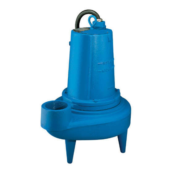
Submersible Sewage Ejector
83 West Drive, Brampton
Ontario, Canada L6T 2J6
Phone: (905) 457-6223
Fax: (905) 457-2650
®
Series:
3SE-L
1.5 & 2HP
1750RPM, 60Hz
(Single Seal)
Form No. 132724-Rev. C
Advertisement
Table of Contents

Related Manuals for Barnes 3SE-L Series


Summary of Contents for Barnes 3SE-L Series
- Page 1 Manual Index BARNES ® INSTALLATION and OPERATION MANUAL Submersible Sewage Ejector Series: 3SE-L 1.5 & 2HP 1750RPM, 60Hz (Single Seal) IMPORTANT! Read all instructions in this manual before operating pump. As a result of Crane Pumps & Systems, Inc. constant product improvement program, product changes may occur.
-
Page 2: Table Of Contents
SEAL TOOL KIT ( see parts list) PRESSURE GAUGE KIT (see parts list) Other brand and product names are trademarks or registered trademarks of their respective holders. ® Barnes is a registered trademark of Crane Pumps & Systems, Inc 1994, 2002, 3/06, 9/06 Alteration Rights Reserved... -
Page 3: Safety First
SAFETY FIRST! Please Read This Before Installing Or Operating Pump. This information is provided for SAFETY and to PREVENT Do not block or restrict discharge hose, as discharge hose EQUIPMENT PROBLEMS. To help recognize this information, may whip under pressure. observe the following symbols: IMPORTANT! Warns about hazards that can result in WARNING! - DO NOT wear loose clothing that may... -
Page 4: Pump Specifications
SECTION: A - PUMP SPECIFICATIONS: DISCHARGE ....3” NPT, Vertical UPPER BEARING: LIQUID TEMPERATURE .. 104°F (40°C) Continuous 1.5 & 2HP ..Single Row, Ball, Oil Lubricated MOTOR HOUSING ..Cast Iron ASTM, Class 30 Load ..... Radial VOLUTE ......Cast Iron ASTM, Class 30 LOWER BEARING: SEAL PLATE .... -
Page 5: General Information
B-3) Storage: Short Term - Barnes Pumps are manufactured for effi cient performance following short inoperative periods in storage. For best results, pumps can be retained in storage, as factory assembled, in a dry atmosphere with constant temperatures for up to six (6) months. -
Page 6: Start-Up Operation
As the motor is oil fi lled, no lubrication or other maintenance is required, and generally Barnes Pumps will give very TEMPERATURE SENSOR ELECTRICAL RATINGS reliable service and can be expected to operate for years on... -
Page 7: Electrical Data
MODEL VOLT/PH NEMA INSUL. FULL LOCKED CORD CORD CORD WINDING RESISTANCE (Nom) START CLASS LOAD ROTOR SIZE TYPE EMERSON G.E. CODE AMPS AMPS inch (mm) MAIN-START MAIN-START 3SE1524L 230/1 1750 16.0 44.6 12/3 SOOW / SOW 0.61 (15.5) 1.21 - 2.80 3SE1594L 200-230/3 1750... -
Page 8: Service And Repair
1) Inspect motor chamber for oil level and contamination and pressure and remove the gauge assembly. If the pressure repair as required per paragraph F-1. does not hold, then the leak must be located and repaired. 2) Inspect impeller and body for excessive build-up or clogging and repair as required per paragraph F-2. - Page 9 To test the temperature sensor (P1 / P2, optional), check for continuity between the wire leads (see Figure 10). If found to be defective, contact a motor service station or Barnes Pumps Service department. Inspect motor winding for shorts and check resistance values. Check rotor for wear. If rotor or the stator windings are defective, the complete motor must be replaced.
- Page 10 POWER CORD (30) CONTROL CORD (32) CAP SCREW (16) CAP SCREW (16) LOCKWASHER (11) LOCKWASHER (11) COMPRESSION FLANGE (30a) COMPRESSION FLANGE (32a) SNAP RING (41) SNAP RING (41) O-RING (40) O-RING (40) TERMINAL BLOCK (23) TERMINAL BLOCK (38) TERMINAL TERMINAL FIGURE 5 Motor - Slide lower bearing (6) and motor shaft squarely Reconnect motor and optional control leads to the underside...
- Page 11 Stationary Member (31A) Motor & Bearing Bracket Rotating Member (31B) Polished Face Out Stationary Seal Plate (1) Seal Pusher Seal Pusher Bullet FIGURE 8 FIGURE 7 Important ! - DO NOT Hammer On The Seal DO NOT interchange seal components, replace the entire Pusher- It Will Damage The Seal Face.
-
Page 12: Replacement Parts
SECTION: G REPLACEMENT PARTS G-2 PART NUMBER: The part number consists of a six (6) digit number, which appears in the catalog. A one or two letter suffi x may follow this G-1 ORDERING REPLACEMENT PARTS: number to designate the design confi guration. This number is When ordering replacement parts, ALWAYS furnish the used for ordering and obtaining information. - Page 13 FIGURE 10...
-
Page 14: Trouble Shooting
TROUBLE SHOOTING CAUTION ! Always disconnect the pump from the electrical power source before handling. If the system fails to operate properly, carefully read instructions and perform maintenance recommendations. If operating problems persist, the following chart may be of assistance in identifying and correcting them: MATCH “CAUSE”... -
Page 15: Cross-Section (Figure 11)
FIGURE 11... -
Page 16: Exploded View (Figure 12)
FIGURE 12... -
Page 17: Parts List
PARTS KITS SEAL REPAIR KIT: 1.5 & 2.0HP.... P/N 130181 (+) 8, 10, 31, 40 SERVICE: 1.5 & 2.0HP ......P/N 130208 (◊) 2, 3, 6, 8, 10, 14, 15, 18, 25, 31, 34, 35, 40, 41 TOOLS: Seal Pusher......P/N- TL-21360 Bullet ........ - Page 18 TABLE 2 - POWER & SENSOR CORD SETS TERMINAL BLOCK MODEL NO 30 FT. POWER 50 FT. POWER 100 FT. POWER POWER 3SE1524L 109498XC 109498XF 109498XL 103760 3SE1594L 109492XC 109492XF 109492XL 103586 3SE1544L 103742XC 103742XF 103742XL 103583 3SE1554L 103742XC 103742XF 103742XL 103583 3SE2024L...
-
Page 19: Warranty
Limited 24 Month Warranty Crane Pumps & Systems warrants that products of our manufacture will be free of defects in material and workmanship under normal use and service for twenty-four (24) months after manufacture date, when installed and maintained in accordance with our instructions.This warranty gives you speci• c legal rights, and there may also be other rights which vary from state to state. -
Page 20: Warranty Registration
IMPORTANT! WARRANTY REGISTRATION Your product is covered by the enclosed Warranty. To complete the Warranty Registration Form go to: http://www.cranepumps.com/ProductRegistration/ If you have a claim under the provision of the warranty, contact your local Crane Pumps & Systems, Inc. Distributor. RETURNED GOODS RETURN OF MERCHANDISE REQUIRES A “RETURNED GOODS AUTHORIZATION”.
Need help?
Do you have a question about the 3SE-L Series and is the answer not in the manual?
Questions and answers