Table of Contents
Advertisement
IMPORTANT!
Read all instructions in this manual before operating pump.
As a result of Crane Pumps & Systems, Inc., constant product improvement program,
product changes may occur. As such Crane Pumps & Systems reserves the right to
change product without prior written notifi cation.
A Crane Co. Company
420 Third Street
Piqua, Ohio 45356-0603
Phone: (937) 778-8947
Fax: (937) 773-7157
www.cranepumps.com
BARNES
BARNES
SERVICE MANUAL
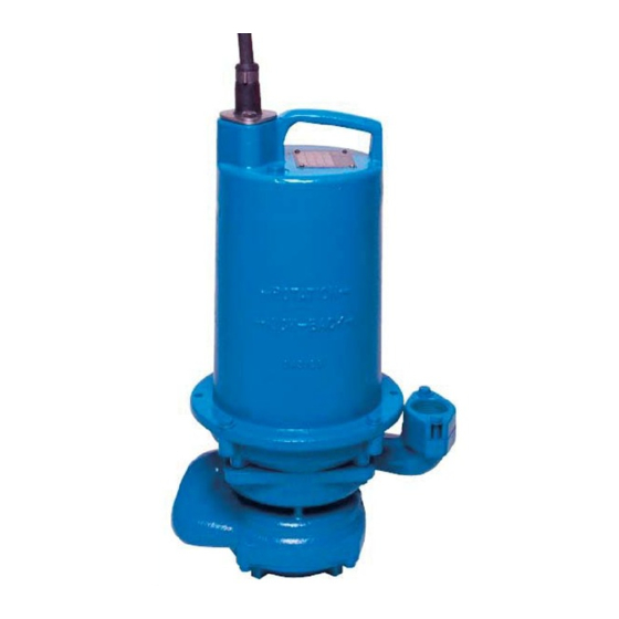
OGP 2 HP Pump
®
83 West Drive, Bramton
Ontario, Canada L6T 2J6
Phone: (905) 457-6223
Fax: (905) 457-2650
Form No. SM118049-Rev. B
Advertisement
Table of Contents

Subscribe to Our Youtube Channel
Related Manuals for Barnes OGP 2 HP


Summary of Contents for Barnes OGP 2 HP
- Page 1 BARNES BARNES ® SERVICE MANUAL OGP 2 HP Pump IMPORTANT! Read all instructions in this manual before operating pump. As a result of Crane Pumps & Systems, Inc., constant product improvement program, product changes may occur. As such Crane Pumps & Systems reserves the right to change product without prior written notifi...
-
Page 2: Table Of Contents
NOTES ....................35 Other brand and product names are trademarks or registered trademarks of their respective holders. ® Barnes is a registered trademark of Crane Pumps & Systems, Inc © Crane Pumps & Systems, Inc. 2004, 7/06 Alteration Rights Reserved... -
Page 3: Safety First
SAFETY FIRST! Please Read This Before Installing Or Operating Pump. WARNING! - DO NOT pump hazardous materials This information is provided for SAFETY and to PREVENT (fl ammable, caustic, etc.) unless the pump is specifi cally EQUIPMENT PROBLEMS. To help recognize this information, designed and designated to handle them. -
Page 4: Tool List
TOOL LIST • Cresent Wrench • Hammer • Brass Flat Punch • 1/2” Wrench Combination End • 2 - 3/16” Flat Blade Screwdrivers • 1/4” Nut Driver • 1/8” Allen Wrench • 5/16” Allen Wrench • Needle-Nose Pliers • 4” PVC Coupler •... -
Page 5: Ogp 2Hp Disassembly
OGP 2HP DISASSEMBLY Visual Inspection of Pump Quick visual inspections can save time. A visual Examination of the pump for damage to cords, controls, or cutter, and a thorough electrical check should be performed to determine a pumps condition. Cut Cords Check the cord(s) for any cuts or gouges. - Page 6 Check the Resistance - (Multi-Meter) CAUTION: Perform this test with the pump off. This test is to check for open circuits or loose connections and also to determine if the motor windings are good. To perform this test, touch one meter lead to the white pump lead, touch the other meter lead to the black pump lead, record the reading.
- Page 7 Moveable Alignment To prevent the moveable from leaking, make a visual check from the face of the moveable to the lower pump bracket. The face of the moveable needs to be parallel to the lower pump bracket. When assembled on the pump, the moveable face will be perpendicular to the centerline of the pump discharge. Figure Figure A A...
-
Page 8: Cutter Removal
Cutter Removal CAUTION: Sharp edges, use caution when removing cutter. NOTE: Prior to disassembly, mark castings with a permanent marker on all joints to assist in realignment. With the pump lying on its side, remove the cutter retaining screw and washer. The screw has green loctite so apply heat to the screw, wedge a fl... -
Page 9: Suction Cover Removal
Suction Cover Removal Loosen and remove the four 5/16 hex head bolts and lock washers from the rim of the suction cover. Remove suction cover and square-ring from bottom of volute. Inspect square-ring for signs of wear and abrasion. First Stage Impeller Removal With the pump lying on its side, use a hammer and tap on the face of the impeller vanes. -
Page 10: Volute
Volute Loosen and remove the four 5/16 hex head bolts and lock washers from the volute. Remove volute and square ring from pump. Inspect square-ring for signs of wear and abrasion. Loosen and remove the two 5/16 bolts and fl at washers from the volute discharge. Remove volute discharge fl... -
Page 11: Oil Removal, Pressure Check
Oil Removal, Pressure Check Remove plug from motor housing and drain all oil from motor chamber by setting unit on its side. If cooling oil is not going to be reused or recycled, it must be disposed of per local and environmental standars CAUTION! Oil can be under pressure and hot! -
Page 12: Second Stage Impeller Removal
Second Stage Impeller Removal The impeller and spacer sleeve can be removed by using a 7/8” open end wrench or a cresent wrench and turning counterclockwise while holding the motor shaft stationary with a screwdriver. CAUTION: Use Caution not to damage threads on shaft. NOTE: With impeller removed, the seal spring is relaxed and some oil may seep from the motor housing. -
Page 13: Shaft Seal
Shaft Seal CAUTION: Handle seal parts and shaft with extreme care. Do not scratch or mar lapped or machined surfaces. Remove spring and rotating member from shaft. Examine all seal parts and especially contact faces. Inspect seal for signs of wear, such as uneven wear tracks on stationary members, chips, and scratches on either seal face. -
Page 14: Motor Housing
Motor Housing NOTE: Position unit upright, using 4” PVC coupler to avoid resting unit on the lower shaft. Loosen 5/16” hex bolts and lockwashers from cable clamp on motor housing. Remove cord from motor housing by pulling straight up while using a rocking motion. Remove retaining snap ring with a medium fl... -
Page 15: Motor Housing
Motor Housing (con’t) Remove 5/16” hex head bolts and lockwashers from motor housing and vertically lift motor housing from intermediate coupling. Remove square ring from intermediate coupling. Inspect square ring for signs of wear and abrasion... -
Page 16: Motor
Motor Remove the four long 1/4” hex head stator bolts and carefully remove the motor stator from the rotor. A pair of screwdrivers may be helpful in removing the motor stator. CAUTION: USE CARE NOT TO DAMAGE MOTOR WINDINGS WHEN REMOVING MOTOR STATOR. -
Page 17: Bearings
Bearings Remove the bearing from the rotor shaft by removing snap rings from shaft and using a wheel puller or an arbor press. Upper rotor bearing may be removed from rotor shaft with a bearing puller. NOTE: Pictures below show bearing markings on outside of rotor. When replacing bearings, be careful not to damage the rotor or shaft threads. -
Page 18: Stationary Seal
Stationary Seal Remove the stationary seal from the seal plate by pressing out with a fl at tipped screwdriver. Examine all seal parts and especially contact faces. -
Page 19: Ogp 2Hp Assembly
OGP 2HP ASSEMBLY Bearing to Pump Rotor When replacing the bearing, be careful not to damage the rotor or shaft threads. Using an arbor press, hold the rotor and press the bearing on the rotor shaft, applying force to the inner race of the bearing only. Install top retaining ring on rotor shaft. -
Page 20: Motor
Motor Slide motor rotor, with bearings into seal plate. Set wave spring on top of upper bearing, hold in place with small amount of grease. BOSS Set motor stator over rotor being sure that stator drops fl at against boss in coupling. Place end bell on top of motor and insert the hex stator bolts in motor and torque to 17 in/lbs. -
Page 21: Wiring Diagram
Wiring Diagram Wiring Diagram For Emerson Electric Motor Figure Figure D D Wiring Diagram For Franklin Electric Motor Figure Figure E E... -
Page 22: Seal
Seal Clean and oil stationary seal cavity in seal plate. Slide seal guide (see parts list - Seal Tool Kit) over motor shaft. Lightly oil (DO NOt grease) outer surface of stationary seal. Press stationary seal fi rmly into seal plate using a seal pusher. Make sure the stationary member is in straight. Nothing but the seal pusher is to come in contact with seal face. -
Page 23: Impeller
Impeller Assemble spacer sleeve to second stage impeller by applying green loctite to 1” threads on spacer sleeve and thread onto impeller. Assemble impeller and spacer sleeve assembly onto motor shaft with machined step fi tting inside I.D. of seal spring by turning clockwise while holding shaft stationary with a screwdriver. -
Page 24: Volute
Volute Lubricate square ring and place on groove in bottom seal plate. Place volute on seal plate being careful not to damage square ring. Place four 5/16” bolts and washers on and tighten equally to 11 ft/lbs. NOTE: Volute discharge must line up 180 degrees from motor leads. -
Page 25: First Stage Impeller
First Stage Impeller Check and make sure spacer sleeve extends through second stage and into fi rst stage of volute. Visually check fi rst stage impeller mating surface and make sure that it is smooth and fl at around the 5/8 threads. Then install impeller onto shaft by threading impeller clockwise until it stops against spacer sleeve. -
Page 26: Cutter
Cutter Screw radial cutter on shaft turning clockwise, holding motor shaft stationary with a screwdriver. Radial cutter should be fl ush with shredding ring on suction side to within ±.020. Replace counter sunk washer and 1/4” allen screw and tighten to 6.5 ft/lbs. Use green loctite on threads. CAUTION: CUTTING SURFACES ARE SHARP! NOTE: Tap the cutter tooth with a fl... -
Page 27: Discharge Flange
Discharge Flange Install o-ring and mount volute discharge fl ange with 5/16” hex head bolts and fl at washers. NOTE: Check the 1-1/4” NPT threads on the mounting fl ange and make sure they face the correct direction. The chamfered side of the NPT tapped hole should be facing up. -
Page 28: Motor Housing
Motor Housing Lubricate and set square ring into bore on intermediate coupling. Install ground wire in end bell if removed (Use proper bolt to secure ground lug). Place fi berglass sleeve over motor and ground leads if removed. Pull wires through opening in top of motor housing while lowering motor housing onto seal plate. - Page 29 Motor Housing (con’t) Lubricate o-ring and slide terminal block back into housing. Make sure terminal block is engaged and install snap ring to retain terminal block. Tighten bolts and lock washers into motor housing. If there were optional pump features such as a fl oat, re-install those at this time also. Tighten 5/16” hex head bolts and lockwashers into motor housing.
-
Page 30: Pin Placement Diagram
Pin Placement Diagram Figure Figure F F SINGLE PHASE - 240 VOLT AC Figure Figure G G Wiring Harness Wiring Harness SINGLE PHASE - 240 VOLT AC AUF and AUE SERIES Figure Figure H H... -
Page 31: Perform Pressure Check
Perform Pressure Check NOTE: This is to be performed with no oil in housing. CAUTION: MAKE CERTAIN THAT CORD SET IS ATTACHED TO PUMP. PERFORMING THE PRESSURE CHECK WITHOUT THE CORD SET ON MAY CAUSE THE TERMINAL BLOCK TO BLOW OUT. To check the pump for any seal leaks, attach the pressure gauge assembly using pipe sealant. -
Page 32: Replacing Oil
Replacing Oil Motor housing - Set unit upright and refi ll with (see chart for type and amount) new cooling oil. Fill to just above the end bell, (top), of the motor, as an air space must remain in the top of the motor housing to compensate for oil expansion. -
Page 33: Ogp 2Hp Exploded View
OGP 2HP Exploded View Figure Figure K K... -
Page 34: Parts Kits/List
PARTS KITS Seal Repair Kit ...P/N: 116664 Item #’s: 6, 7, 13, 15, 20, 25, 33, 36, 38 Overhaul Kit ....P/N: 116665 Item #’s: 3, 5, 6, 7, 9, 13, 15, 20, 25, 28, 29, 33, 36, 38 Cutter Kit ....P/N: 116666 Item #’s: 5, 6, 7, 9, 13, 15, 36 PARTS LIST ITEM... -
Page 35: Notes
Notes... - Page 36 CRANE PUMPS & SYSTEMS, INC. 420 THIRD STREET PIQUA, OHIO 45356-0603 - U.S.A.
Need help?
Do you have a question about the OGP 2 HP and is the answer not in the manual?
Questions and answers