Deagostini MODEL SPACE FAST & FURIOUS DODGE CHARGER R/T Manual
Pack 1
Hide thumbs
Also See for MODEL SPACE FAST & FURIOUS DODGE CHARGER R/T:
Advertisement
Quick Links
Advertisement

Subscribe to Our Youtube Channel
Related Manuals for Deagostini MODEL SPACE FAST & FURIOUS DODGE CHARGER R/T


Summary of Contents for Deagostini MODEL SPACE FAST & FURIOUS DODGE CHARGER R/T
- Page 1 pack...
- Page 2 FCA US LLC and used under license by Premium and Collectibles Trading Co. Ltd. ©2019 FCA US LLC. Stage 2 ©️ 2019 Editorial Planeta DeAgostini S.A.U. Todos los derechos reservados. Steering wheel and first ©️ 2019 De Agostini Publishing Italia S.p.A.
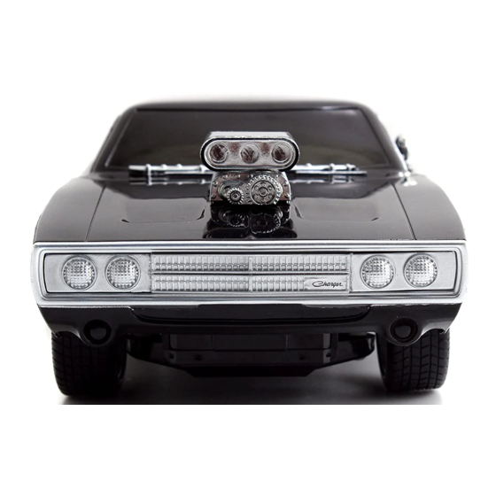
- Page 3 BONNET AND STAGE SUPERCHARGER In this stage you will assemble the bonnet with the impressive supercharger in the middle, one of the most distinctive and characteristic elements of the 1970 Dodge Charger R/T. PIECES FOR THIS STAGE PIECES FOR THIS STAGE 1O 1P 1A Bonnet Supercharger pulley...
- Page 4 STAGE 1 USEFUL TIP When handling the body parts, it is a good idea to take a few small precau- tions to protect the paintwork from scratches. We recommend you prepare a clean work area and that you work on a cloth or sheet of cardboard, so as to protect the pieces against damage.
- Page 5 STAGE 1 what you built in the last step upside down and ttach the right mount 1C to the end of the butterfly place it over the upper half of the air intake. Join all the valve plate shaft on the right hand side of the air intake. pieces together with four type AP screws.
- Page 6 STAGE 1 1.10 1.11 two type AP screws, join the pulley spacer 1J and sing the bracket 1O and the front cover 1N of the the cover of the supercharger unit 1N. supercharger together, ensuring that the pieces are facing the same way as shown in the illustration. Join the pieces together with two type AP screws.
- Page 7 STEERING WHEEL STAGE AND FIRST WHEEL Here we will show you how to assemble the steering wheel and the front left wheel of your Charger R/T. PIECES FOR THIS STAGE 2A Steering wheel 2B Steering wheel hub cover 2C Steering column 2D Steering wheels spokes 2E Front right tyre 2F Rim (outside)
- Page 8 STAGE 2 ttach the steering wheel spokes 2D to the outer part of the steering wheel 2A by aligning the four mounting holes and inserting four BM type screws. nsErt the cylindrical end of the steering column 2C into the middle of the steering wheel (2A and 2D). Use a CM type screw to fix it in place.
- Page 9 STAGE 2 the steering wheel hub cover 2B onto the ttach centre of the spokes by pressing it, ensuring that it is facing the same way as shown in the illustration. at the front left tyre 2E: on one side you will see the word “inside”...
- Page 10 STAGE 2 three HM type screws into the holes in the nsErt inside of the rim. Tighten the screws to join the two parts of the rim (2H and 2F). lacE the washer 2I in the middle of the outside of the rim.
- Page 11 NOSE WITH GRILLE AND FRONT STAGE HEADLAMPS Thanks to the new parts attached, you can start assembling the nose of your Dodge Charger R/T. PIECES FOR THIS STAGE 3A Chromed profile 3B Front upper panel 3C Frame front headlamps (x 2) 3D Glass cover front headlamp (x 4) 3E Radiator grille 3F Front headlamp unit (x 2)
- Page 12 STAGE 3 osition the front upper panel 3B so that you can work on its inner side. Mount the pieces of the front left headlamps in the following order: frame 3C, two glass covers 3D (the linchpins on the frame must match up with the corresponding holes in the glass covers) and the unit 3F.
- Page 13 STAGE 3 the chromed profile 3A, the radiator grille 3E and the front upper panel 3B together. Once you are sure all the pieces are facing the right way, join them together with eight type AP screws. nsErt the indicator frame 3I, the glass cover 3H and the respective indicator unit into the left hole in the front lower panel 3J.
- Page 14 STAGE 3 the second indicator on the front lower ount panel 3J in the same way as you did on the left: insert the frame 3I, the glass cover 3H and the indicator unit into the panel; fix in place with two type DM screws. the front lower panel 3J and the upper panel 3B together, ensuring that the...
- Page 15 FRONT LEFT BRAkE AND STAGE SUSPENSION You can now make the brake disc and attach the wheel to the elements of the suspension. PIECES FOR THIS STAGE 4A Front left brake caliper 4H Shock absorber piston 4P Front left brake caliper baseplate 4B Front left wheel hub 4I Spring CM Screw 1.7×3 mm (x 10)*...
- Page 16 STAGE 4 the parts of the brake disc (4D and 4E) together by inserting the linchpins on piece 1 into the corresponding holes in piece 2, as shown in the illustration. the wheel hub 4B and the convex side of the brake disc 4E together, by inserting the centering linchpin into the small hole in the brake disc 4E.
- Page 17 STAGE 4 ttach the upper part of the shock absorber 4G lign the upper suspension arm 4F with the to the inside of the suspension dome 4J using corresponding holes in the side of the dome 4J, ensuring an EM type screw. that the pieces are facing the same way as shown in the illustration.
- Page 18 STAGE 4 4.10 the completed suspension and brake together. Use two type CM screws to join piece 2 4K and piece 1 of the spindle 4C. 4.11 nsErt piece 1 of the ball joint 4L into the corresponding hole in the upper arm 4F. Now align it with the wishbone of piece 1 of the spindle 4C.
Need help?
Do you have a question about the MODEL SPACE FAST & FURIOUS DODGE CHARGER R/T and is the answer not in the manual?
Questions and answers