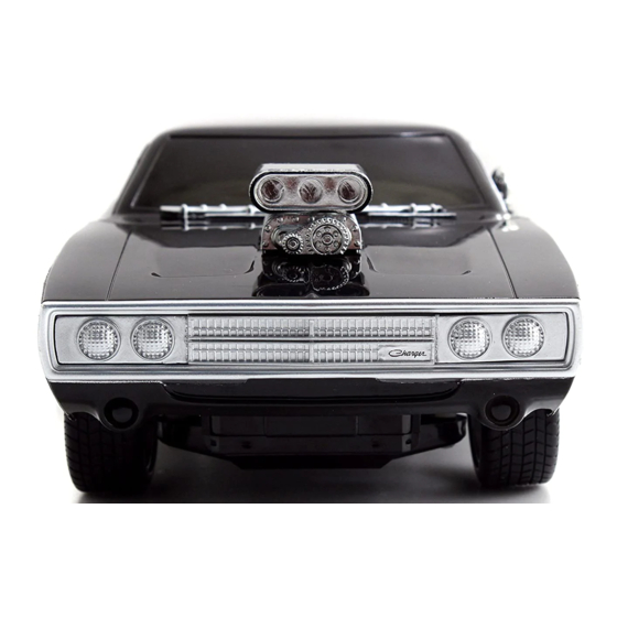
Deagostini MODEL SPACE FAST & FURIOUS DODGE CHARGER R/T Manual
Pack 12
Hide thumbs
Also See for MODEL SPACE FAST & FURIOUS DODGE CHARGER R/T:
Table of Contents
Advertisement
Quick Links
Advertisement
Table of Contents

Related Manuals for Deagostini MODEL SPACE FAST & FURIOUS DODGE CHARGER R/T


Summary of Contents for Deagostini MODEL SPACE FAST & FURIOUS DODGE CHARGER R/T
- Page 1 pack pack...
- Page 2 FCA US LLC and used under license by Connecting the wires and Premium and Collectibles Trading Co. Ltd. ©2019 FCA US LLC. ©️ 2019 Editorial Planeta DeAgostini S.A.U. testing the lights Todos los derechos reservados. ©️ 2019 De Agostini Publishing Italia S.p.A.
- Page 3 THE ELECTRONIC THE ELECTRONIC STAGE STAGE CONTROL UNIT CONTROL UNIT In this assembly session you will attach the electronic control unit to your model car. The unit controls the lights and sound effects. PIECES FOR THIS STAGE 46A Electronic control unit DM Screws 1.7×3x5 mm (x 5)* 46B Wiring and switch for sound effects of horn and engine 46C Wiring and switch for the lights...
- Page 4 STAGE 46 STAGE 46 46.1 the connector on the wiring for the sound nsert effects 46B into socket 1F of the electronic control unit 46A; the connector on the wiring for the lights 46C into socket 1G; and the wiring of the dashboard lights 46D into socket 1H.
- Page 5 STAGE 46 STAGE 46 46.3 nsert the connector on the wire of the speaker 45B into socket 1E in the control unit. Then, connect the wire of the battery holder to socket 1D. 46.4 the sound. Insert three AAA* batteries into the battery holder and switch on.
- Page 6 STAGE 46 STAGE 46 46.5 the switch on the wiring for the sound effects 46B once. The speaker 45B ress should reproduce the sound of the horn. Press switch 46B again, and you should hear the sound of the engine. To stop the sound, press the switch again. Use the switch on the battery holder 44A to turn the system off.
- Page 7 CONNECTING THE CONNECTING THE WIRES AND TESTING WIRES AND TESTING STAGE STAGE THE LIGHTS THE LIGHTS In this assembly session you will connect the wires of the brake light, headlights and rear lights to the control unit. You will then perform a simple test to check that the lights work properly. PIECES FOR THIS STAGE 47A Wiring and switch for the brake light 47D Type A wire grommet (x 3)
- Page 8 STAGE 47 STAGE 47 47.1 the connector on the wiring for the brake light 47A to socket 1B in onneCt the electronic control unit 46A; the connector of the wiring for the headlights 47B to socket 1A, and that of the rear lights 47C to socket 1C. 47.2 you are going to check if the lights work properly.
- Page 9 STAGE 47 STAGE 47 47.3 ress the switch on the wiring 46C to turn on the rear lights 47C, the headlights 47B, and the dashboard lights 46D. 47.4 ress the switch on the wiring for the brake light 47A to increase the intensity of the rear lights 47C (or to switch them on if the switch on the lights 46C is turned off).
- Page 10 STAGE 47 STAGE 47 A USEFUL TIP At the end of this session, put the chassis on the supplied stands to prevent the tyres from deforming. 47.5 you have finished testing the model car’s electronic functions, turn off the switch on the battery holder 44A and remove the battery holder cover 43B and the three AAA batteries.
- Page 11 ATTACHING THE ATTACHING THE STAGE STAGE WIRES TO THE CHASSIS WIRES TO THE CHASSIS In this assembly session you will attach the wires to the chassis. You will also attach four hooks to the floor pan. Follow our instructions carefully, using the illustrations to help you. PIECES FOR THIS STAGE 48A Floor pan 48B Hooks (x 4)
- Page 12 STAGE 48 STAGE 48 48.1 the wire for the rear lights 47C between the three pairs of linchpins located on the middle and rear sections of the chassis (30A and 31A). Also, insert the wire for the battery holder 44A between the first two pairs of linchpins, those on the middle section of the chassis.
- Page 13 STAGE 48 STAGE 48 48.3 rouP together the following wires between the pairs of linchpins on the front platform 21A: those of the switch for the horn and engine sound effects 46B; those of the front headlights 47B; those of the brake light switch 47A;...
- Page 14 STAGE 48 STAGE 48 48.5 two of the hooks 48B into nsert the two holes on the floor pan 48A, next to the central tunnel. 48.6 nsert the remaining two hooks 48B into the holes on the other side of the tunnel.
- Page 15 INSTALLING THE INSTALLING THE STAGE STAGE GEAR LEVER GEAR LEVER In this assembly session you will connect the wires of the brake light, headlights, and rear lights to the electronic control unit. You will then perform a simple test to check that the lights work properly. PIECES FOR THIS STAGE 49A Gear lever 49E Middle section of the transmission tunnel...
- Page 16 STAGE 49 STAGE 49 49.1 laCe the shift rail 49C on the centre console 49D, and join the two components together using two type AP screws. 49.2 the thinner end of the gear lever 49A into nsert the corresponding housing in the centre console 49D, ensuring that the ball at the opposite end fits into its housing.
- Page 17 STAGE 49 STAGE 49 49.3 ttaCh the piece you have just assembled to the middle of the floor pan 48A, ensuring it faces the same way as in the illustration. Secure the centre console 49D to the floor pan with two type AP screws. 49.4 the floor pan and the middle section of the transmission tunnel 49E, by inserting the two tabs into the corresponding slots.
- Page 18 STAGE 49 STAGE 49 49.5 the floor pan over and attach it to the middle section of the transmission tunnel 49E using two type AP screws. STAGE 49 FINAL RESULT You have now installed the gear lever and the middle section of the transmission tunnel on the floor pan.
- Page 19 ASSEMBLING THE ASSEMBLING THE STAGE STAGE FIRE EXTINGUISHER FIRE EXTINGUISHER In this assembly session you will assemble the fire extinguisher and attach it to the floor pan. Follow our instructions very carefully, using the illustrations to help you. PIECES FOR THIS STAGE 50A Fire extinguisher stand 50E Brackets (x 2) 50B Fire extinguisher (front)
- Page 20 STAGE 50 STAGE 50 50.1 the front and back of the fire extinguisher 50B and 50C together. Secure them with two type AP screws. 50.2 ress the pressure gauge 50D into the hole in the front of the fire extinguisher 50B.
- Page 21 STAGE 50 STAGE 50 50.3 the floor pan 48A you were working on at the end of the last assembly session. Attach the fire extinguisher stand 50A to the middle section of the transmission tunnel 49E, ensuring it faces the same way as in the illustration. 50.4 ount the fire extinguisher on the...
- Page 22 STAGE 50 STAGE 50 50.5 lIGn the two brackets 50E with the corresponding holes in the right side of the floor pan 48A, next to the hooks that you mounted in assembly session 47. Secure each of the two brackets with two type AP screws.
Need help?
Do you have a question about the MODEL SPACE FAST & FURIOUS DODGE CHARGER R/T and is the answer not in the manual?
Questions and answers