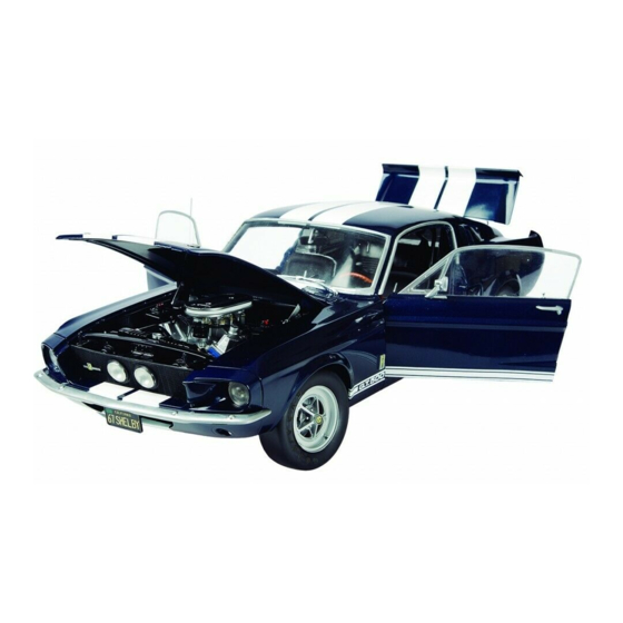
Summary of Contents for Deagostini MODEL SPACE Ford Mustang SHELBY GT-500 1967
- Page 2 Battersea Studios 2, 82 Silverthorne Road, London SW8 3HE, UK © 2016 De Agostini UK Ltd © 2016 Editorial Planeta DeAgostini S.A. © 2016 De Agostini Publishing Italia S.p.A. All rights reserved. Warning: Not suitable for children under the age of 14.
-
Page 3: Parts Supplied
STEP BY STEP Step by step #81 Left front wing PARTS SUPPLIED WITH THIS ISSUE PARTS SUPPLIED 81-1 LEFT FRONT FENDER 81-1 Care of the parts It is important to handle and store your parts carefully, whether they are to be used in the assembly stage they come with or during later stages. - Page 4 STEP BY STEP Step by step #81 Step 81-A Step 81-B Although the left front wing (81-1) should not be fitted Here is what the left front wing will look like in place. yet, you should take the opportunity to test-fit it. The two parts arrowed on the wing engage with the two arrowed points on the chassis.
-
Page 5: Chassis Front Panel
STEP BY STEP Step by step #82 Chassis front panel PARTS SUPPLIED WITH THIS ISSUE PARTS SUPPLIED 82-1 CHASSIS FRONT PANEL 82-2 LEFT HOOD BRACKET 82-1 82-3 1.8 X 3MM SCREWS (MP09) 82-4 RIGHT HOOD BRACKET 82-5 2.3 X 4MM SCREWS (MD06) Spare parts 82-2 Some extra screws and other... - Page 6 STEP BY STEP Step by step #82 Step 82-A Step 82-B Align the indicated post on the left hood bracket (82-2) Insert the post into the hole. with the indicated hole in the chassis front panel (82-1). Step 82-C Step 82-D Turn the panel over and tighten an MP09 screw (82-3) Insert the right hood bracket (82-4) into the hole at the...
- Page 7 STEP BY STEP Step by step #82 Step 82-E Step 82-F As before, hold the bracket in position and secure it with Now retrieve the left front wing (81-1). Place the two a second MP09 screw (82-3). indicated holes in the chassis front panel onto the two posts in the wing.
- Page 8 STEP BY STEP Step by step #82 Step 82-I Here is the chassis front panel connected to the wing. STAGE COMPLETE Note: the model shown here is the prototype.
- Page 9 STEP BY STEP Step by step #83 Right front wing PARTS SUPPLIED PARTS SUPPLIED WITH THIS ISSUE 83-1 RIGHT FRONT WING 83-2 2.3 X 4MM SCREWS (MD06) Spare parts Some extra screws and other 83-1 parts may be provided as spares. Store them safely in labelled 83-2 plastic bags, so that you can...
- Page 10 STEP BY STEP Step by step #83 Step 83-A Step 83-B Align the indicated posts at the front of the wing (83-1) with the holes in the Secure the parts with two MD06 right side of the front chassis panel from the previous stage. screws (83-2).
- Page 11 STEP BY STEP Step by step #84 Body PARTS SUPPLIED PARTS SUPPLIED WITH THIS ISSUE 84-1 BODY 84-2 2.3 X 4MM SCREWS (MD06) Spare parts Some extra screws and other parts may be provided as spares. Store them safely in labelled 84-1 plastic bags, so that you can identify them easily should you...
- Page 12 STEP BY STEP Step by step #84 Step 84-A To avoid damaging the paintwork on any of the body parts, you should work on a soft surface, like a cloth. The posts on the inside of the front wings will engage with the indicated holes in the front of the body (84-1).
- Page 13 STEP BY STEP Step by step #84 Step 84-D Hold the parts together and turn them over so you can access the underside. Tighten one MD06 screw (84-2) into the indicated hole. Step 84-E Tighten the second MD06 screw into the arrowed hole on the other side.
- Page 14 STEP BY STEP Step by step #84 Step 84-G Once the parts are secure, there should be a small gap between the the bottom of the wing and the doorpost. Step 84-H Here is how the body should now look. STAGE COMPLETE Note: the model shown here is the prototype.


Need help?
Do you have a question about the MODEL SPACE Ford Mustang SHELBY GT-500 1967 and is the answer not in the manual?
Questions and answers