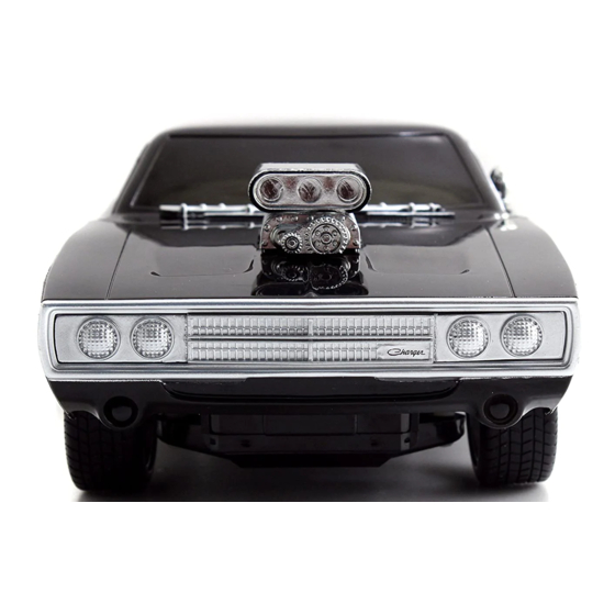
Deagostini MODEL SPACE FAST & FURIOUS DODGE CHARGER R/T Manual
Pack 6
Hide thumbs
Also See for MODEL SPACE FAST & FURIOUS DODGE CHARGER R/T:
Advertisement
Quick Links
Advertisement

Summary of Contents for Deagostini MODEL SPACE FAST & FURIOUS DODGE CHARGER R/T
- Page 1 pack...
- Page 2 Dodge, HEMI and related logos, vehicle model names and trade dress are trademarks of FCA US LLC and used under license by Premium and Collectibles Trading Co. Ltd. ©2019 FCA US LLC. Stage 22 ©️ 2019 Editorial Planeta DeAgostini S.A.U. Assembling the engine Todos los derechos reservados. housing (I) ©️...
- Page 3 ASSEMBLING STAGE THE FRONT PLATFORM In this assembly session you will attach the front platform to the front section of the chassis. Follow our instructions and the accompanying illustrations carefully. PIECES FOR THIS STAGE PIECES FOR THIS STAGE 21A Front platform AM Screws 2×4 mm (x 8)* AP Screws 1.7×4 mm (x 3)* * Some of the parts are spares.
- Page 4 STAGE 21 21.1 the chassis and engine block you assembled in the last session. Put the piece upside down on your work surface. Insert the linchpins on the ends of the left and right bank exhaust pipes 18F and 19F into the corresponding holes in the front platform 21A. At the same time, line up the holes in the platform with the corresponding holes in the rear beam of the front section of the chassis 5A.
- Page 5 STAGE 21 21.2 the new piece back over. Insert two AP screws into the holes indicated in the illustration, and tighten them to attach the left and right exhaust pipe tubes to the platform 21A.
- Page 6 STAGE 21.3 o conclude this work session, insert three AM screws into each side of the platform 21A, as shown in the illustration, to hold all the pieces together. STAGE 21 FINAL RESULT You have now attached the front platform to the chassis.
- Page 7 ASSEMBLING STAGE THE ENGINE HOUSING (I) In this assembly session you will start to assemble the engine housing, which is the area under the bonnet that contains the engine of your model. PIECES FOR THIS STAGE 22A Left panel 1 22B Left panel 2 AM Screws 2×4 mm (x 4)* * Some of the parts are spares.
- Page 8 STAGE 22 22.1 this assembly session by lining up the ou sTarT three holes in the left panel 1 22A with the three holes in the left panel 2 22B.
- Page 9 STAGE 22 22.2 you have aligned the two panels of the engine housing correctly, join them together by inserting a type AM screw into each of the three holes.
- Page 10 STAGE USEFUL TIP When you have join pieces together with screws, it is best to insert and tighten them in a certain order, so as to distribute the pressure as evenly as possible and avoid damaging the parts in question. In this case, we recommend that you insert the central screw first, followed by the two either side.
- Page 11 ASSEMBLING STAGE THE ENGINE HOUSING (II) In this assembly session you will continue to assemble the engine housing, which is the area under the bonnet that contains the engine of your model. PIECES FOR THIS STAGE 23A Right panel 1 23B Right panel 2 AM Screws 2×4 mm (x 4)* * Some of the parts are spares.
- Page 12 STAGE 23 23.1 egin by lining up the three holes in the right panel 1 23A with the three holes in the right panel 2 23B.
- Page 13 STAGE 23 USEFUL TIP Sometimes, when assembling the parts, it can be difficult to understand which side of the model the parts belong to. This is the case, for example, in sessions 22 and 23. Note, however, that the pieces which go on the left side are marked with a letter “L”, while those which go on the right side are marked with the letter “R”.
- Page 14 STAGE 23 23.2 you have aligned the two panels, join them with three AM screws. STAGE 23 FINAL RESULT You have finished the right wall of the engine housing. Keep it in a safe place until you are ready to attach it to your model.
-
Page 15: Assembling The Battery
ASSEMBLING THE STAGE BATTERY In this assembly session you will attach the battery pieces together. Then, you will install the battery inside the left panel of the engine housing. PIECES FOR THIS STAGE 24A Battery housing 24G Positive terminal 24B Battery 24H Positive cable 24C Battery cover 24I Ground cable... - Page 16 STAGE 24.1 24.2 the battery cover 24C onto the battery 24B, over what you have built so far and put the making sure the pieces are facing the same way as battery housing 24A under the battery 24B. Ensure those in the illustration (use the battery recycling label the pieces are facing the same way as those in the as a reference).
- Page 17 STAGE 24 24.4 nserT the second clamping bar 24E into the bracket 24D, and push it right down. 24.5 the left panel of the engine housing that you assembled in assembly session 22. Align the two linchpins on the battery housing 24A with the two widest holes in the left panel 22B.
- Page 18 STAGE 24.7 the linchpin on the negative nserT terminal 24F into the hole in the battery cover 24C, as shown in the illustration. Now connect the free end of the ground cable 24I to the linchpin on the top righthand side of the left panel 1 of the engine housing 22A.


Need help?
Do you have a question about the MODEL SPACE FAST & FURIOUS DODGE CHARGER R/T and is the answer not in the manual?
Questions and answers