
Related Manuals for Deagostini MODEL SPACE Ford Mustang Shelby GT-500 1967


Summary of Contents for Deagostini MODEL SPACE Ford Mustang Shelby GT-500 1967
- Page 2 Battersea Studios 2, 82 Silverthorne Road, London SW8 3HE, UK © 2016 De Agostini UK Ltd © 2016 Editorial Planeta DeAgostini S.A. © 2016 De Agostini Publishing Italia S.p.A. All rights reserved. Warning: Not suitable for children under the age of 14.
-
Page 3: Parts Supplied
STEP BY STEP Step by step #05 The left seat backrest PARTS SUPPLIED WITH THIS ISSUE PARTS SUPPLIED 5-1 LEFT SEAT BACK (REAR) 5-2 LEFT SEAT BACK (FRAME) 5-3 SCREWS 2.3 X 4 (MP01) 5-4 LEFT SEAT BACK (FRONT) INSTALLATION DIAGRAM... - Page 4 STEP BY STEP Step by step #05 Step Step Before starting the assembly of the left seat backrest, Before starting the assembly of the left seat backrest, Place the seat back frame onto the reverse of the seat Place the seat back frame onto the reverse of the seat locate the four holes on the reverse of the seat back rear back rear.
- Page 5 STEP BY STEP Step by step #05 Step Before tting the screws, make sure that the two parts are Before tting the screws, make sure that the two parts are ush along the edges. Step Take one of the MP01 screws (5-3) and place it in the top Take one of the MP01 screws (5-3) and place it in the top right hole.
- Page 6 STEP BY STEP Step by step #05 Step Step To improve the strength of the join between the seat To improve the strength of the join between the seat Place the seat front into place on the rest of the assembly. Place the seat front into place on the rest of the assembly.
-
Page 7: The Exhaust System
STEP BY STEP Step by step #06 The exhaust system PARTS SUPPLIED WITH THIS ISSUE PARTS SUPPLIED 6-1 LOWER SILENCER HALF 6-2 UPPER SILENCER HALF 6-3 SCREWS 2.3 X 4 (MP01) 6-4 RIGHT SILENCER INLET PIPE 6-5 RIGHT EXHAUST PIPE 6-6 LEFT SILENCER INLET PIPE 6-7 LEFT EXHAUST PIPE 6-8 RIGHT TAILPIPE... - Page 8 STEP BY STEP Step by step #06 Step The lower silencer half (6-1) has two cutouts at each end, for mounting the silencer inlet and exhaust pipes. front rear Step Step Step Test- t the right silencer inlet pipe (6-4) Also check the t of the right exhaust Combine the upper (6-2) and lower into the cutout at the rear of the lower...
- Page 9 STEP BY STEP Step by step #06 Step Step Hold the two halves of the silencer apart and insert Hold the two halves of the silencer apart and insert Hold the right silencer inlet pipe in place and insert the Hold the right silencer inlet pipe in place and insert the the right silencer inlet pipe into the rectangular hole right exhaust pipe into the rounded hole.
- Page 10 STEP BY STEP Step by step #06 Step Take the right tailpipe (6-8) and align the tip with the hole in the end of the right exhaust pipe (6-5). The tip and the hole are both D-shaped. Test- t the tailpipe and then secure it with a drop of instant adhesive or superglue.
- Page 11 STEP BY STEP Step by step #07 Front wheel and tyre PARTS SUPPLIED WITH THIS ISSUE PARTS SUPPLIED 7-1 FRONT WHEEL 7-2 FRONT TYRE INSTALLATION DIAGRAM Technical Tip To make it easier to mount the tyre onto the wheel, you may want to soften it by applying gentle heat from a hair dryer or by immersing it in hot water.
- Page 12 STEP BY STEP Step by step #07 Step Step Soften the tyre (7-2) as outlined in the Technical Tip box Soften the tyre (7-2) as outlined in the Technical Tip box Seat the tyre properly on the wheel and ensure that it ts Seat the tyre properly on the wheel and ensure that it ts on page 12, then t it onto the wheel (7-1) while it is evenly all the way around on both sides.
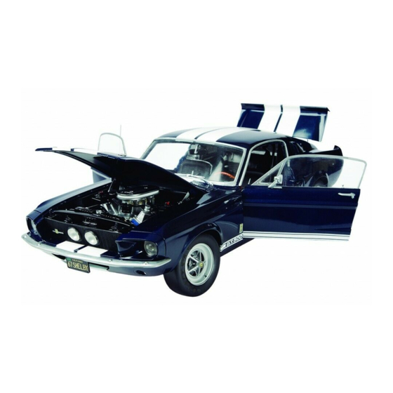
- Page 13 STEP BY STEP Step by step #07 The Shelby logo Many parts of the real Mustang Shelby GT-500 carry the Shelby logo. Your scale model reproduces the logos at each of these locations: the centre of each wheel, the bottom of each front fender, the radiator grille, the tail, the steering wheel and the dashboard.
- Page 14 STEP BY STEP Step by step #07 Handling and storing parts The parts of your model are detailed reproductions of the parts of the original car. Because of this, they are very fragile, so it’s important to handle them with extreme care when assembling and storing them in order to avoid any damage.
- Page 15 STEP BY STEP Step by step #08 Right front brake PARTS SUPPLIED WITH THIS ISSUE PARTS SUPPLIED 8-1 STEERING KNUCKLE 8-2 BRAKE DISC SHIELD 8-3 BRAKE DISC 8-4 BRAKE CALIPER 8-5 SCREWS 1.2 X 3 (MD04) 8-6 SCREWS 2.3 X 3 (MD02) 8-7 SHELBY LOGO WHEEL COVER Spare parts...
- Page 16 STEP BY STEP Step by step #08 Step Step Take the steering knuckle (8-1) and the brake disc shield Take the steering knuckle (8-1) and the brake disc shield Push the steering knuckle (8-1) into place on the brake disc Push the steering knuckle (8-1) into place on the brake disc (8-2), and align the studs with the holes (arrowed).
- Page 17 STEP BY STEP Step by step #08 Step Step The disc should be held in place by the caliper, but it Fix the parts together with an MD04 screw (8-5). should still be able to rotate freely. Step Insert the brake disc assembly into the inside of the wheel.
- Page 18 STEP BY STEP Step by step #08 Step Tighten an MD02 screw (8-6) into the hole in the centre of the wheel. Tighten the screw into place while holding the brake assembly in position. Step Push the Shelby logo wheel cover (8-7) into the hole in the centre of the wheel, covering the MD02 screw.
Need help?
Do you have a question about the MODEL SPACE Ford Mustang Shelby GT-500 1967 and is the answer not in the manual?
Questions and answers