Deagostini MODEL SPACE FAST & FURIOUS DODGE CHARGER R/T Manual
Pack 15
Hide thumbs
Also See for MODEL SPACE FAST & FURIOUS DODGE CHARGER R/T:
Advertisement
Quick Links
Advertisement

Related Manuals for Deagostini MODEL SPACE FAST & FURIOUS DODGE CHARGER R/T


Summary of Contents for Deagostini MODEL SPACE FAST & FURIOUS DODGE CHARGER R/T
- Page 1 pack...
- Page 2 FCA US LLC and used under license by Assembling the car body Premium and Collectibles Trading Co. Ltd. ©2019 FCA US LLC. ©️ 2019 Editorial Planeta DeAgostini S.A.U. Todos los derechos reservados. Stage 63 Mounting the door hinges ©️...
-
Page 3: Attaching The Steering Wheel
ATTACHING THE STAGE STEERING WHEEL In this assembly session you will attach the steering wheel to the steering column, and connect the wiring for the lights and sound effects. PIECES FOR THIS STAGE 61A Middle section of the car body STEERING WHEEL AND DASHBOARD These items are not toys;... - Page 4 STAGE 61 61.1 the steering wheel that you assembled in assembly session 2. In the hole at the end of the steering column 2C, screw and then unscrew one type JM screw (provided with session 60), to prepare the hole for the next step. 61.2 lide the steering column washer 57C onto the end of the piece made up of the left and right covers (57A and 57B).
- Page 5 STAGE 61 61.3 the steering system by lifting the front of the model and turning the steering wheel clockwise and counter clockwise. When you do this, the front wheels should turn. 61.4 61.5 the ends of the following wires: wiring for the the wire grommet 56E.
- Page 6 STAGE 61 61.6 emove the screws holding the rods on the middle section of the car body 61A in place, and remove the rods. These parts are not needed for the car; their only function was to protect this large part during transport. STAGE 61 FINAL RESULT You have now attached the steering wheel to your model.
- Page 7 ASSEMBLING STAGE THE CAR BODY In this assembly session you will join together the two parts of the car body you have been given. Please follow our instructions and the accompanying illustrations carefully. PIECES FOR THIS STAGE 62A Rear section of the car body QM screws 2X4 mm (x 5)* AM screws 2.3X5 mm (x 4)* Screwdriver...
- Page 8 STAGE 62 62.1 the middle section of the car body 61A, attached to the last issue, and join it to the rear section 62A, as shown in the illustration. A USEFUL TIP When joining metal parts, such as those of the car body, self-tapping screws are used.
- Page 9 STAGE 62 62.3 the two sections of the car body from the outside, by ecuRe inserting two type AM screws in the corresponding holes in the left side. 62.4 epeat on the right side, using another two type AM screws.
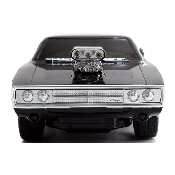
- Page 10 STAGE 62 OvErvIEw In this illustration you can see the two parts of the car body joined together, in red. The illustration shows you how it will look when it is attached to the chassis. The Dodge Charger R/T is a coupe with a fastback body style: there are only two doors, and the rear window is so steeply slanted that it is almost parallel to the rear of the car.
- Page 11 MOUNTING THE DOOR STAGE HINGES In this assembly session you will attach the door hinges and their mounting brackets to the car body. Follow our instructions and the explanatory images very carefully. PIECES FOR THIS STAGE 63A Left door hinge 63D Right door hinge mounting bracket 63B Left door hinge mounting bracket AP screws 1.7X4 mm (x 3)*...
- Page 12 STAGE 63 63.1 the left door hinge 63A (to distinguish it from the right door hinge 63C, look at the pieces shown on the previous page). Insert the linchpin on hinge 63A into the middle hole in the mounting bracket 63B, marked with the letter L.
- Page 13 STAGE 63 63.3 liGn the tabs on the left door hinge mounting bracket 63B with the holes in the middle section of the car body 61A, located behind the left door. Attach the bracket to the car body with two type HM screws.
- Page 14 STAGE 63 63.4 of the car body 61A, align the n the RiGht Side two tabs on the right door hinge mounting bracket 63D with the corresponding holes. Use another two type HM screws to attach the bracket. STAGE 63 FINAL RESULT You have now attached the door hinges and their mounting brackets to the car body.
- Page 15 INSTALLING THE STAGE QUARTER PANELS (I) In this assembly session you will install the left quarter panel. Please follow our instructions and the accompanying illustrations very carefully. PIECES FOR THIS STAGE 64A Left quarter panel frame AM screws 2X4 mm (x 10)* * Some of the parts are spares.
- Page 16 STAGE 64 64.1 the left quarter panel frame 64A to the car ttach body (pieces 61A and 62A). Ensure all the pieces face the same way as those in the illustration. Secure with two type AM screws. 64.2 ow inSeRt three type AM screws in the front part of the left quarter panel frame 64A, as shown in the illustration.
- Page 17 STAGE 64 64.3 insert one type AM screw into the middle section of the quarter panel frame 64A. 64.4 insert two type AM screws into inally the corresponding mounting holes in the back of the quarter panel frame 64A.
- Page 18 STAGE 64 A USEFUL TIP To check that the chassis is ready to be attached to the car body, control the tread of each tyre: turn the chassis upside down, as shown in the photo, and check the direction of the diagonal lines.
- Page 19 STAGE INSTALLING THE QUARTER PANELS (II) In this assembly session you will install the right quarter panel frame. Please follow our instructions and the accompanying illustrations very carefully. PIECES FOR THIS STAGE 65A Right quarter panel frame AM screws 2X4 mm (x 10)* * Some of the parts are spares.
- Page 20 STAGE 65 65.1 ttach the right quarter panel frame 65A to the car body (pieces 61A and 62A). Ensure all the pieces face the same way as those in the illustration. Secure with two type AM screws. 65.2 insert three type AM screws in the front part of the right quarter panel frame 65A, as shown in the illustration.
- Page 21 STAGE 65 65.3 insert one type AM screw into the middle section of the quarter panel frame 65A.
- Page 22 STAGE 65 65.4 inally insert two type AM screws into the corresponding mounting holes in the back of the quarter panel frame 65A. STAGE 65 FINAL RESULT Now both of the quarter panel frames are firmly attached to the body of your model car.
Need help?
Do you have a question about the MODEL SPACE FAST & FURIOUS DODGE CHARGER R/T and is the answer not in the manual?
Questions and answers