
Related Manuals for E+E Elektronik EE895


Summary of Contents for E+E Elektronik EE895
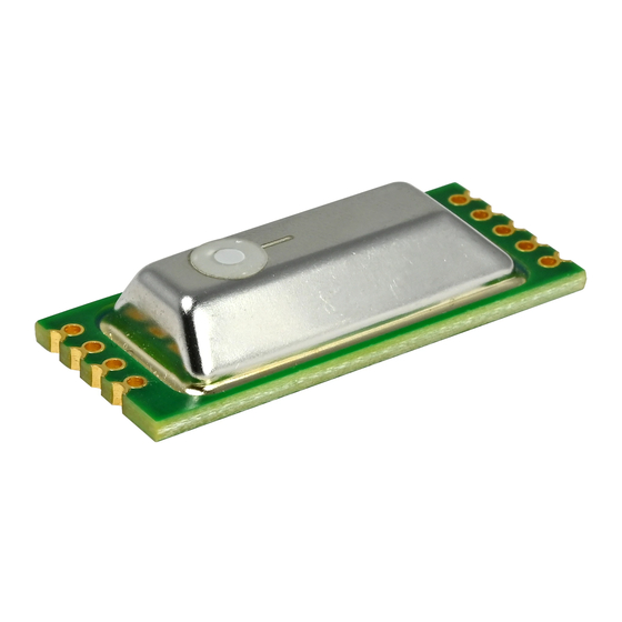
- Page 1 User Manual EE895 MINIATURE SENSOR MODULE FOR CO , TEMPERATURE AND BAROMETRIC PRESSURE BA_EE895 // V1.0 // technical data are subject to change...
- Page 2 E+E Elektronik Ges.m.b.H. doesn‘t accept warranty and liability claims neither upon this publication nor in case of improper treatment of the described products. The document may contain technical inaccuracies and typographical errors. The content will be revised on a regular basis. These changes will be implemented in later versions. The described products can be improved and changed at any time without prior notice.
-
Page 3: Table Of Contents
3.7.1 EE895 Connected to USB Interface ........................10 3.7.2 EE895 in Battery Powered Devices ........................10 3.7.3 EE895 Connected to a KNX Bus ........................11 Digital Interface ..........................11 C Interface ..............................11 4.1.1 Modbus Protocol Over I C Interface........................11 4.1.2... -
Page 4: Introduction
The sensor module can be mounted using several mounting methods. Please observe chapter 3 for mounting recommendations and descriptions. The use of the EE895 other than described in this manual is not recommended. The manufacturer cannot be held responsible for damages as a result of incorrect handling, installation and maintenance of the device. -
Page 5: Product Description
EPA (Electrostatic Protected Area) using ESD protective packaging. The EE895 is packed in stacks of ESD trays with 50 pieces each. The tray dimension is 354.2 x 278.6 x 23.8 mm (13.94 x 10.97 x 0.94 inch). -
Page 6: Mounting Recommendation
Fig. 2 Recommended PCB footprint Mounting Recommendation The EE895 is not intended for reflow soldering and consequently it does not feature a moisture sensitivity level rate (MSL). Nevertheless, for storage and handling it shall be regarded as compatible with MSL 1. -
Page 7: Ee895 Block Diagram
The IR-L does not have to be powered continuously, as it needs power supply during the measurement cycle t only, see Figure 6. Between the measurement cycles the current consumption of IR-L is meas approx. 0.1 µA. User Manual EE895 Miniature Sensor Module for CO , T and p... - Page 8 EN pin by an external host controller. When the EN pin is pulled-down to the logic Low 0 (≤0.4 V), the internal voltage regulator of EE895 is switched off and the current consumption is typically 1 µA (max 2 µA).
-
Page 9: Electrical Characteristics
Pin 7 – ISEL connected to ground: EE895 features I C interface: Mode Note SCL (serial clock) External pull-up resistor to V+ (bus high voltage level) is required. SDA (serial data) External pull-up resistor to V+ (bus high voltage level) is required. -
Page 10: Typical Applications
3.7.2 EE895 in Battery Powered Devices Fig. 11 Example battery powerd devices Pin 7 - ISEL is connected to the ground → the EE895 features I C interface. User Manual EE895 Miniature Sensor Module for CO , T and p... -
Page 11: Ee895 Connected To A Knx Bus
The VCC_EM and the VCC_IO are connected to the typical 5 V bus voltage. The I C host keeps the EE895 enabled with the pin 3 – EN and can read the values at any time, pin 6 - RDY is not used. -
Page 12: I 2 C Simplified Protocol
The EE895 module supports repeated START or STOP conditions between the request packet and the response packet. If a START condition and an address match are detected, the EE895 will stay active until a STOP condition is received or an idle timeout of 500 ms occurs. This might increase the power consumption and self-heating. - Page 13 (i.e. the SDA line is not pulled down). If a START condition and an address match are detected, the EE895 will stay active until a STOP condition is received or an idle timeout of 500 ms occurs. The measured data is available as a 16 bit integer and is expressed in SI units:...
-
Page 14: Uart Interface
The interface settings are: Baud rate 9600, 8 Data, No parity, 1 Stop bit (9600 8 N 1) The slave address and the interface settings are fixed, they cannot be changed by the user. The EE895 module shall be addressed according to the specification “Modbus over serial line V1.02”, http://www.modbus.org/docs/Modbus_over_serial_line_V1_02.pdf Modbus frame description (screenshot taken from the “Modbus over serial line Specification and Imple-... -
Page 15: Ee895 Commands
Please note: When reading the serial number or the sensor name, it is always necessary to read all 8 registers, even if the desired information requires less. 4.4.2 General Settings The following functions allow for EE895 settings. These are stored in the RAM, therefore they are volatile. Measuring mode: continuous or single shot Function code Register address... -
Page 16: Co 2 Parameter Settings
The filter coefficient is user selectable and affects the response time of the EE895. A higher filter coefficient leads to smoother output data and to longer response time, see figure 12. Figure 13 shows the number of samples required to reach 63% or 90% of a CO step as function of the filter coefficient. - Page 17 Fig. 13 Step response vs. samples Fig. 14 Step response vs. filter coefficient User Manual EE895 Miniature Sensor Module for CO , T and p...
-
Page 18: Appendix 1 : Technical Note An0103
Packet Format For Write Function Code 0x06 ................20 Packet Format for Write Multiple Function Code 0x10 ..............21 Data Encoding of Float Values ......................21 IEEE 754 Format ............................21 Modbus Floating Point Format ........................21 User Manual EE895 Miniature Sensor Module for CO , T and p... - Page 19 Communication Address Qunatity of Registers Modbus Function Address Code 03, 04 Response from the E+E Modbus device: N * Register Modbus Byte Function Code Address Count 03, 04 User Manual EE895 Miniature Sensor Module for CO , T and p...
- Page 20 Packet Format For Write Function Code 0x06 Request: Communication Address Register Value Modbus Function Address Code Response from the E+E Modbus device: Communication Address Register Value Modbus Function Address Code User Manual EE895 Miniature Sensor Module for CO , T and p...
- Page 21 E+E devices use the Modbus floating point format. The byte pairs 1, 2 and 3, 4 are inverted as follows. SEEEEEEE EMMMMMMM MMMMMMMM MMMMMMMM Byte 3 Byte 4 Byte 1 Byte 2 User Manual EE895 Miniature Sensor Module for CO , T and p...
-
Page 22: Appendix 2: Technical Data
1) With data averaging for smooth output signal. 2) The pressure dependency of a device without pressure compensation: 0.14 % of measured value / mbar. 3) Recommended under normal operating conditions in building automation. User Manual EE895 Miniature Sensor Module for CO , T and p... - Page 23 User Manual EE895 Miniature Sensor Module for CO , T and p...
- Page 24 HEADQUARTERS SUBSIDIARIES E+E Elektronik Ges.m.b.H. E+E Elektronik Germany E+E Elektronik France E+E Elektronik Korea Langwiesen 7 info@epluse.de info@epluse.fr Tel: +82 31 732 6050 A-4209 Engerwitzdorf Tel: +33 4 74 72 35 82 info@epluse.co.kr Office Bad Homburg Austria Tel: +49 6172 13881-0...
Need help?
Do you have a question about the EE895 and is the answer not in the manual?
Questions and answers