Advertisement
QUICK GUIDE
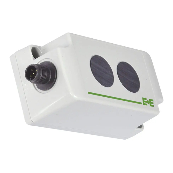
EE8915 - CO
Find this document and further product information on our website at www.epluse.com/EE8915.
CONNECTION DIAGRAM
Important note:
» The manufacturer cannot be held responsible for personal injuries or damage to property as a result of incorrect
handling, installation, wiring, power supply and maintenance of the device.
» For failure-free operation and performance according to the specs, the GND supply and the GND analogue output
must be wired separately. Internally, the GNDs are connected to each other on the electronics board.
FIX INSTALLED CABLE
Core number
Function
1
10 - 35 V DC supply
2
GND supply
3
GND analogue output
4
Current output
5
Voltage output
ERROR INDICATION ON THE ANALOGUE OUTPUT
The EE8915 features an error indication on the analogue output according to NAMUR recommendations (factory setting: disabled).
The feature can be enabled with the EE-PCS Product Configuration Software, see full user guide at www.epluse.com/EE8915.
Output signal
NAMUR signal level
0-5 V
5.5 V
0-10 V
11 V
4-20 mA
21 mA
0-20 mA
21 mA
STATUS LEDs
Green LED
Sensor for Railway Applications
2
Green LED
Red LED
flashing
Red LED
off
on
flashing
M12 CONNECTOR
4
3
5
1
2
M12 device plug
GND analogue output
front view
Power supply 10 - 35 V DC*
*The supply circuit must be fused with ≤ 8A
= Normal operation
= Normal operation
= Failure. Contact E+E after sales service.
= Failure. Also indicated on the analogue output (NAMUR indication
enabled). The failure might be temporary, caused for instance by
overheating. If the flashing persists, contact E+E after sales service.
Voltage output
2
Current output
4
5
1
GND
3
V
mA
+
-
Advertisement
Table of Contents

Related Manuals for E+E Elektronik EE8915


Summary of Contents for E+E Elektronik EE8915
- Page 1 ERROR INDICATION ON THE ANALOGUE OUTPUT The EE8915 features an error indication on the analogue output according to NAMUR recommendations (factory setting: disabled). The feature can be enabled with the EE-PCS Product Configuration Software, see full user guide at www.epluse.com/EE8915.
- Page 2 The arrows on the enclosure indicate the flow direction. When correctly installed, a small amount of air flows through the divided probe into the EE8915 enclosure, where the CO sensing cell is located, and back into the duct. Very important...
Need help?
Do you have a question about the EE8915 and is the answer not in the manual?
Questions and answers