
Related Manuals for E+E Elektronik EE895


Summary of Contents for E+E Elektronik EE895
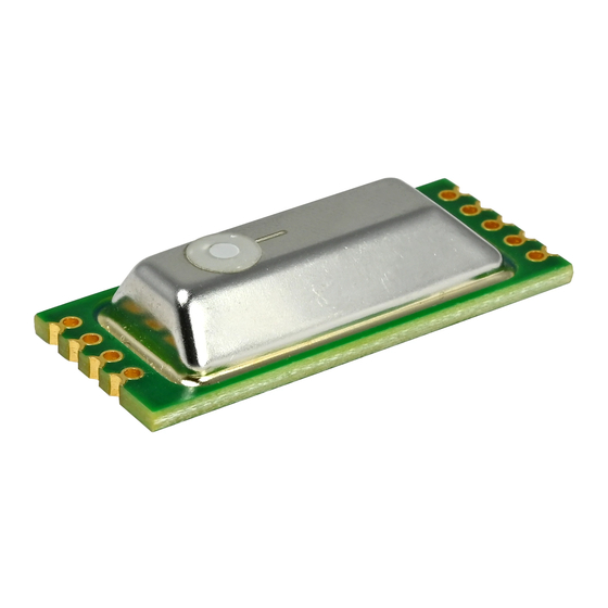
- Page 1 User Manual EE895 Miniature Sensor Module for CO Temperature and Barometric Pressure...
-
Page 2: Table Of Contents
3.7.1. EE895 Connected to USB Interface......................12 3.7.2. EE895 in Battery Powered Devices ......................12 3.7.3. EE895 Connected to a KNX Bus ....................... 13 Digital Interface............................13 C Interface ............................13 4.1.1. Modbus Protocol Over I C Interface ......................13 4.1.2. -
Page 3: General Information
The user manual may not be used for the purposes of competition without the written consent of E+E Elektronik Ges.m.b.H. and may not be forwarded to third parties. Copies may be made for internal purposes. All information, technical data and diagrams included in these instructions are based on the information available at the time of writing. -
Page 4: Safety Instructions
Failing to follow the instructions in this user manual may lead to measurement inaccuracy and device failures. ▪ The EE895 may only be operated under the conditions described in this user manual and within the specification included in chapter 5 Technical Data. ▪... -
Page 5: Environmental Aspects
Environmental Aspects PLEASE NOTE Products from E+E Elektronik Ges.m.b.H. are developed and manufactured in compliance with all relevant environmental protection requirements. Please observe local regulations for the disposal of the device. For disposal, the individual components of the device must be separated according to local recycling regulations. -
Page 6: Handling Instructions
EPA (Electrostatic Protected Area) using ESD protective packaging. The EE895 is packed in stacks of ESD trays with 50 pieces each. The tray dimension is 354.2 x 278.6 x 23.8 mm (13.94 x 10.97 x 0.94 inch) Operating and storage conditions: -40…60 °C (-40…140 °F) -
Page 7: Mounting Recommendation
(MSL). Nevertheless, for storage and handling it shall be regarded as compatible with MSL 1. CAUTION EE895 may only be soldered manually. A max. temperature of 360 °C may be applied for max. 10 s per solder point. -
Page 8: Ee895 Block Diagram
User Manual EE895 EE895 Block Diagram Fig. 3 Block diagram Pin Assignment Bottom view Fig. 4 Pin assignment Pin no. Name Type Comment VCC_EM Power supply Power supply emitter infra-red lamp (IR-L) VCC_IO Power supply Power supply for the microcontroller Input Enable the module. -
Page 9: Pin Description
1 µA (max 2 µA). When pulled-up to the logic state High (≥0.9 V), the EE895 operates normally. If the energy consumption of EE895 is not relevant, the EN pin shall be connected to VCC_IO. The EN pin may not be left open. Pin 6 – RDY (Data ready) - Page 10 Pin 8 – TX_SCL Transmission data / Serial clock Pin 9 – RX_SDA Receiving data / Serial data The function of pins 8 and 9 depends on the interface selected with pin 7 ISEL. Pin 7 – ISEL connected to ground: EE895 features I C interface: Pin no.
-
Page 11: Electrical Characteristics
User Manual EE895 Example: Fig. 7 Example UART interface Electrical Characteristics A DC/DC converter is used to flash the lamp (VCC_EM). Therefore, the supply current is reduced with higher voltage and vice versa. The microcontroller (VCC_IO) is supplied via a linear reglator, hence the supply current is constant. -
Page 12: Typical Applications
3.3 V regulator. The I C host enables the EE895 with pin 3 - EN. By checking the status of pin 6 - RDY (pulled up), the host can read the data as soon as available. After reading the data, EE895 can be disabled with pin 3. -
Page 13: Ee895 Connected To A Knx Bus
The VCC_EM and the VCC_IO are connected to the typical 5 V bus voltage. The I C host keeps the EE895 enabled with the pin 3 – EN and can read the values at any time, pin 6 - RDY is not used. -
Page 14: I 2 C Simplified Protocol
The read pointer is the first register to be set. Additional bytes are answered by the EE895 module with NACK. If more bytes are read than the 8 registers, the EE895 answers with 0xFF (i.e. the SDA line is not pulled down). - Page 15 1) pc ... pressure compensated 2) npc ... not pressure compensated *) Example: 2 575 means 25.75 °C **) Example: 10 130 means 1 013 mbar Tab. 7 Data availability from the EE895 Miniature Sensor Module Example for reading all measurands (7-bit address shifted): EE895 Request [Hex]: S BC 00 P Slave address...
-
Page 16: Uart Interface
The interface settings are: Baud rate 9600, 8 Data, No parity, 1 Stop bit (9600 8 N 1) The slave address and the interface settings are fixed, they cannot be changed by the user. The EE895 module shall be addressed according to the specification “Modbus over serial line V1.02”, see https://modbus.org/docs/Modbus_over_serial_line_V1_02.pdf. -
Page 17: Modbus Register Map
User Manual EE895 Modbus Register Map Following Modbus register map is valid for both, the I C and the UART interface. The measured data is saved as 32 bit floating point values (data type FLOAT) and as 16 bit signed integer values (data type INTEGER), please refer to Tab. -
Page 18: Ee895 Commands
When reading the serial number or the sensor name, it is always necessary to read all 8 registers, even if the desired information requires less. 4.5.2. General Settings The following functions allow for EE895 settings. These are stored in the RAM, therefore they are volatile. Measuring mode: continuous or single shot Register Function... - Page 19 [Bit 0]: Data ready. The data are available for read out. 0 = busy, 1 = ready [Bit 1]: Trigger ready. The EE895 is ready for new measurement cycle. The minimum time interval between two triggers is 10 s. 0x03...
-
Page 20: Co 2 Parameter Settings
The filter coefficient is user selectable and affects the response time of the EE895. A higher filter coefficient leads to smoother output data and to longer response time, see figure Fig. 12. Fig. 13 shows the number of samples required to reach 63% or 90% of a CO step as function of the filter coefficient. -
Page 21: Technical Data
User Manual EE895 Fig. 13 Step response vs. filter coefficient 5 Technical Data Measurands Measurement principle Dual wavelength non-dispersive infrared technology (NDIR) Measuring range 0...2 000 / 5 000 / 10 000 ppm Accuracy @ 25 °C (77 °F) and 1 013 mbar (14.7 psi) 0...2 000 ppm < ±(50 ppm +2 % of measured value) 0...5 000 ppm < ±(50 ppm +3 % of measured value) 0...10 000 ppm... - Page 22 User Manual EE895 Temperature (T) Measuring range -40…60 °C (-40...140 °F) Accuracy ±0,5 °C (±0.9 °F) @ 24 V DC, 20 °C (68 °F) General Digital interface (pin-selectable) I²C Up to 100 kbit/s UART 9 600 Baud, 8 bits, no parity, 1 stop bit Module control Enable pin Continuous operation / power down...
- Page 23 T +39 02 2707 86 36 info.it@epluse.com E+E Elektronik Korea Ltd. T +82 31 732 6050 info.kr@epluse.com E+E Elektronik Corporation T +1 847 490 0520 info.us@epluse.com Version v1.6 | 06-2023 | © Copyright E+E Elektronik Ges.m.b.H. | Modification rights reserved.
Need help?
Do you have a question about the EE895 and is the answer not in the manual?
Questions and answers