
Related Manuals for E+E Elektronik EE895


Summary of Contents for E+E Elektronik EE895
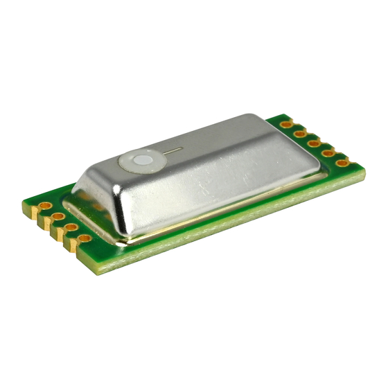
- Page 1 User Manual EE895 MINIATURE SENSOR MODULE FOR CO , TEMPERATURE AND BAROMETRIC PRESSURE BA_EE895 // v1.3 // Modification rights reserved...
- Page 2 E+E Elektronik Ges.m.b.H. does not accept warranty and liability claims neither upon this publication nor in case of improper treatment of the described products. The document may contain technical inaccuracies and typographical errors. The content will be revised on a regular basis.
-
Page 3: Table Of Contents
Typical Applications .............................11 3.7.1 EE895 Connected to USB Interface ........................11 3.7.2 EE895 in Battery Powered Devices ........................11 3.7.3 EE895 Connected to a KNX Bus ........................12 Digital Interface ..........................12 C Interface ..............................12 4.1.1 Modbus Protocol Over I C Interface........................12 4.1.2... -
Page 4: Introduction
This symbol indicates safety information. It is essential that all safety information is strictly observed. Failure to comply with this information can lead to personal injuries or damage to property. E+E Elektronik® assumes no liability if this happens. This symbol indicates instructions. -
Page 5: Environmental Aspects
EPA (Electrostatic Protected Area) using ESD protective packaging. The EE895 is packed in stacks of ESD trays with 50 pieces each. The tray dimension is 354.2 x 278.6 x 23.8 mm (13.94 x 10.97 x 0.94 inch). -
Page 6: Hardware
(MSL). Nevertheless, for storage and handling it shall be regarded as compatible with MSL 1. EE895 may only be soldered manually. A max. temperature of 360°C may be applied for max. 10 s per solder point. ESD precautions shall be observed while manually soldering the EE895. -
Page 7: Mounting Via Side Plated Contacts
3.2.2 Mounting via Side Plated Contacts The EE895 can be mounted by manually soldering the plated half-holes onto the host board. T/p sensor Solder 8 mm (0.32") Air inlet through dust filter towards CO sensing cell Solder T/p sensor Fig. 4 Mounting by soldering at the side plated contacts EE895 Block Diagram Fig. -
Page 8: Pin Assignment
EN pin by an external host controller. When the EN pin is pulled-down to the logic Low 0 (≤0.4 V), the internal voltage regulator of EE895 is switched off and the current consumption is typically 1 µA (max 2 µA). - Page 9 Transmission data / Serial clock Pin 9 – RX_SDA Receiving data / Serial data The function of pins 8 and 9 depends on the interface selected with pin 7 ISEL: Pin 7 – ISEL connected to ground: EE895 features I C interface: Mode Note SCL (serial clock) External pull-up resistor to V+ (bus high voltage level) is required.
-
Page 10: Electrical Characteristics
Sampling intervall 15 s (configurable 10 s ... 1 h) Fig. 10 States during a CO sampling interval Further electrical characteristics: Signal Unit Note Clock frequency 100000 Pull-up resistor kΩ Typical 10 kΩ Tab. 6 Electrical characteristics User Manual EE895 Miniature Sensor Module for CO , T and p... -
Page 11: Typical Applications
EE895 in Battery Powered Devices Fig. 12 Example battery powerd devices Pin 7 - ISEL is connected to the ground → the EE895 features I C interface. VCC_EM is supplied by a low ESR super-capacitor and VCC_IO is connected to a typical low drop 3.3 V regulator. -
Page 12: Ee895 Connected To A Knx Bus
The VCC_EM and the VCC_IO are connected to the typical 5 V bus voltage. The I C host keeps the EE895 enabled with the pin 3 – EN and can read the values at any time, pin 6 - RDY is not used. -
Page 13: I 2 C Simplified Protocol
*) Reserved for future use The read pointer is the first register to be set. Additional bytes are answered by the EE895 module with NACK. If more bytes are read than the 8 registers, the EE895 answers with 0xFF (i.e. -
Page 14: Uart Interface
The interface settings are: Baud rate 9600, 8 Data, No parity, 1 Stop bit (9600 8 N 1) The slave address and the interface settings are fixed, they cannot be changed by the user. The EE895 module shall be addressed according to the specification “Modbus over serial line V1.02”, http://www.modbus.org/docs/Modbus_over_serial_line_V1_02.pdf... -
Page 15: Modbus Register Map
3) Examples: For scale 100, the reading of 2550 means a value of 25.5. For scale 50, the reading of 2550 means a value of 51. Tab. 11 I C and UART Modbus register map for 16 bit signed integer values User Manual EE895 Miniature Sensor Module for CO , T and p... -
Page 16: Ee895 Commands
Please note: When reading the serial number or the sensor name, it is always necessary to read all 8 registers, even if the desired information requires less. 4.4.2 General Settings The following functions allow for EE895 settings. These are stored in the RAM, therefore they are volatile. Measuring mode: continuous or single shot Function code Register address... -
Page 17: Co Parameter Settings
The filter coefficient is user selectable and affects the response time of the EE895. A higher filter coefficient leads to smoother output data and to longer response time, see figure Fig. 14. Fig. 15 shows the number of samples required to reach 63% or 90% of a CO step as function of the filter coefficient. - Page 18 Fig. 14 Step response vs. samples Fig. 15 Step response vs. filter coefficient User Manual EE895 Miniature Sensor Module for CO , T and p...
-
Page 19: Technical Data
1) With data averaging, using default filter configuration. 2) The pressure dependency of a device without pressure compensation: 0.14 % of measured value / mbar. 3) Recommended under normal operating conditions in building automation. User Manual EE895 Miniature Sensor Module for CO , T and p... - Page 20 HEADQUARTERS SUBSIDIARIES E+E Elektronik Ges.m.b.H. E+E Elektronik Germany E+E Elektronik France E+E Elektronik Korea Langwiesen 7 info@epluse.de info@epluse.fr Tel: +82 31 732 6050 A-4209 Engerwitzdorf Tel: +33 4 74 72 35 82 info@epluse.co.kr Office Bad Homburg Austria Tel: +49 6172 13881-0...
Need help?
Do you have a question about the EE895 and is the answer not in the manual?
Questions and answers