
Related Manuals for Smartgen HGM7100N Series


Summary of Contents for Smartgen HGM7100N Series
- Page 1 HGM7100N SERIES (HGM7110N/7120N) GENSET CONTROLLER USER MANUAL SMARTGEN (ZHENGZHOU) TECHNOLOGY CO., LTD.
- Page 2 HGM7100N GENSET CONTROLLER USER MANUAL CONTENTS 1 OVERVIEW .............................. 5 2 PERFORMANCE AND CHARACTERISTICS ..................5 3 SPECIFICATION OPERATION ....................... 7 4 OPERATION ............................8 4.1 KEY FUNCTION ..........................8 4.2 CONTROLLER PANEL ........................9 4.3 AUTO START/STOP OPERATION ....................10 4.3.1.
- Page 3 HGM7100N GENSET CONTROLLER USER MANUAL 11 SENSOR SETTING ..........................42 12 COMMISSIONING ..........................43 13 TYPICAL APPLICATION ........................44 14 INSTALLATION ............................46 14.1 FIXING CLIPS ..........................46 14.2 OVERALL DIMENSION ....................... 46 15 TROUBLESHOOTING ........................... 48 HGM7100N Genset Controller 2017-08-26 Version1.0 Page 4 of 48...
- Page 4 HGM7100N GENSET CONTROLLER USER MANUAL OPERATION KEY FUNCTION Table 3 - Key Function Descriptions Icon Function Description Stop running generator in Auto/Manual mode; In stop mode, in case of alarm condition, pressing the button will reset alarm; Stop/ Reset Pressing and holding the button for 3 seconds will test indicator lights (lamp test);...
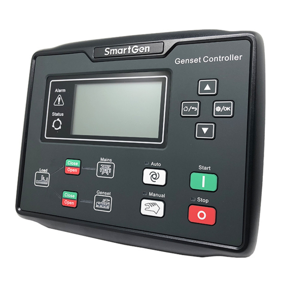
- Page 5 HGM7100N GENSET CONTROLLER USER MANUAL CONTROLLER PANEL Figure 1 - HGM7110N Front Panel Indication Figure 2 - HGM7120N Front Panel Indication NOTE: Part of indicator lights illustration: Table 4 - Alarm Indicator Description Alarm Type Alarm Indicators Warning alarm slowly flash (once per second) Trip alarm slowly flash (once per second) Shutdown alarm...
- Page 6 HGM7100N GENSET CONTROLLER USER MANUAL WIRINGS CONNECTION Compared with HGM7120N, HGM7110N is missing one mains voltage three-phase input terminal. HGM7120N controller back panel is as follows: Figure 3 - HGM7120N Back Panel Table 9 - Terminal Wiring Connection Function Cable Size Remarks 2.5mm Connected with negative of starter battery...
- Page 7 HGM7100N GENSET CONTROLLER USER MANUAL Function Cable Size Remarks Normally open output, rated 8A. Aux. Output 3(16A 250VAC) 2.5 mm Relay normally open volt free contact, rated 16A, volt free contact output. Aux. Output 4(16A 250VAC) 2.5 mm Connected with charger starter’s D+ (WL) terminals. Charger(D+) 1.0mm Being hang up If there is no this terminal.
- Page 8 HGM7100N GENSET CONTROLLER USER MANUAL Function Cable Size Remarks W-phase Voltage Connected to W-phase output of genset (2A fuse 1.0mm Monitoring Input recommended). Gen N2-line Input 1.0mm Connected to N-line output of genset. Mains R-phase Voltage Connected to R-phase of mains (2A fuse recommended). 1.0mm Monitoring Input (HGM7110N without)
- Page 9 HGM7100N GENSET CONTROLLER USER MANUAL SCOPES AND DEFINITIONS OF PROGRAMMABLE PARAMETERS CONTENTS AND SCOPES OF PARAMETERS Table 10 - Parameters Settings and Scope Items Range Default Description Mains 0: 3P4W; 1: 3P3W AC System (0-3) 2: 2P3W 3: 1P2W Provide standard for judging whether mains Mains Rated over/under voltage or not;...
- Page 10 HGM7100N GENSET CONTROLLER USER MANUAL Items Range Default Description Warming time between gen-set switch on and Warming Up Time (0-3600)s high speed running. Radiating time before gen-set stop, after it (0-3600)s Cooling Time unloads. Stop Idle Time (0-3600)s Idle running time while gen-set closing down. Stop electromagnet’s power on time when (0-3600)s ETS Solenoid Hold...
- Page 11 HGM7100N GENSET CONTROLLER USER MANUAL Items Range Default Description If the voltage of charger D+(WL) is lower than the setting value during gen-set normal (0-60.0)V Charge Alt Fail running, controller will initiate fail to charge warning alarms. Maximum crank times when engine starts fail. (1-10)times Start Attempts If reach this number, controller will send start...
- Page 12 HGM7100N GENSET CONTROLLER USER MANUAL Items Range Default Description The setting value is rated voltage percentage. The controller detects it while gen-set Voltage On-load (0-200)% preparing to take the load, if voltage is less than the on-load voltage, gen-set will not enter normal operation period.
- Page 13 HGM7100N GENSET CONTROLLER USER MANUAL Items Range Default Description Over Power Setting (0-1) 0: Disabled; 1: Enabled Reverse Power (0-1) 0: Disabled; 1: Enabled Setting Switch Time from open mains to close generator or (0-7200)s Switching Time from open generator to close mains. Pulse width of mains closed and generator (0-20.0)s Close Delay...
- Page 14 HGM7100N GENSET CONTROLLER USER MANUAL Items Range Default Description When temperature value external connected temperature sensor is higher than High Temp Warning the setting point, controller will initiate high (0-300)ºC Setting temperature warning alarm (judgment only starts after safety on delay expired). Return value and delay value can be set.
- Page 15 HGM7100N GENSET CONTROLLER USER MANUAL DEFINED CONTENTS OF CONFIGURABLE INPUT PORTS 1~7 Table 12 - Enable Programmable Inputs 1~7 (Ground connected is active (B-)) Items Description Users can define content as bellows: Indication: only display without warning and shutdown. Warning: only warning without shutdown. Shutdown: alarm and shutdown immediately.
- Page 16 HGM7100N GENSET CONTROLLER USER MANUAL 13 TYPICAL APPLICATION Figure 5 - HGM7100N Typical Application Figure 6 - HGM7120N Typical Application HGM7100N Genset Controller 2017-08-26 Version1.0 Page 44 of 48...
- Page 17 HGM7100N GENSET CONTROLLER USER MANUAL Figure 7 - Single Phase 2-Wire Connection Diagram Figure 8 - 2Phase 3Wire Connection Diagram NOTE: Expand relay with high capacity in start and fuel output is recommend. HGM7100N Genset Controller 2017-08-26 Version1.0 Page 45 of 48...
- Page 18 14.2 OVERALL DIMENSION Figure 9 - Overall Dimensions HGM7100N series controller can suit for widely range of battery voltage DC (8~35) V. Negative of battery must be connected with the engine shell. Diameter of wire that connects from power supply to battery must be over 2.5mm...
Need help?
Do you have a question about the HGM7100N Series and is the answer not in the manual?
Questions and answers