
Related Manuals for Xterra ERG160 ROWER


Summary of Contents for Xterra ERG160 ROWER
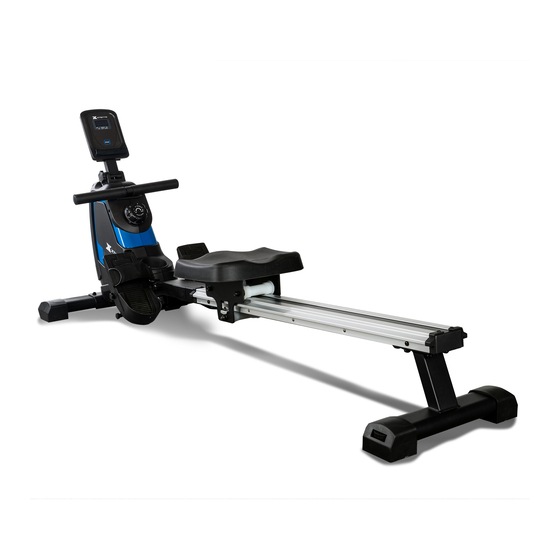
- Page 1 Model: 16804031600 ERG160 ROWER OWNER’S MANUAL PLEASE CAREFULLY READ THIS ENTIRE MANUAL BEFORE OPERATING YOUR NEW ROWER...
-
Page 2: Table Of Contents
TABLE OF CONTENTS Before You Begin ....................3 Important Safety Instructions ................4 ERG160 Assembly Instructions ................8 Operation of Your New Rower ..................14 General Maintenance ..................16 Exploded View Diagram ..................17 Parts List ......................18 Trouble Shooting ....................21 Manufacturer’s Limited Warranty .............. -
Page 3: Before You Begin
If you have any questions or problems with the parts included with your Xterra ERG160 Rower, please do not return the product. Contact us FIRST! If a part is missing or defective call us toll free at 1-888-707-1880. Our Customer Service Staff are available to assist you from 8:30 A.M. -
Page 4: Important Safety Instructions
IMPORTANT SAFETY INSTRUCTIONS WARNING- Read all instructions before using this equipment. Do not operate the rower on deeply padded, plush or shag carpet. Damage to both carpet and rower may result. Before beginning this or any exercise program, consult a physician. This is especially important for ... - Page 5 WARNING DECAL REPLACEMENT The decal shown below has been placed on the rower. If the decal is missing or illegible, please call our Customer Service Department toll-free at 1-888-707-1880 to order a replacement decal.
- Page 6 ERG160 PRE-ASSEMBLY CHECK LIST NO.1 NO.2 NO.3 NO.4 NO.12 R/L NO.38 NO.91 Part No. Description Q'ty Main Frame Slide Rail Front Stabilizer Rear Stabilizer 12L/R Pedals Seat Console Hardware Bag Manual...
- Page 7 ERG160 ASSEMBLY PACK CHECK LIST STEP-1 STEP-2 STEP-3 #55 O D 16*I D 8. 5*1. 5 4PCS #55 O D 16*I D 8. 5*1. 5 2PCS #52 I D 8. 5 4PCS #81 M 8*20 4PCS I D 8. 5 2PCS # 45 M 8*45 2PCS #62 2PCS...
-
Page 8: Erg160 Assembly Instructions
ERG160 ASSEMBLY INSTRUCTIONS 1 SEAT #62 M6*10 2pcs #100 1pc Slide the Seat (38) onto the Slide Rail (2). Attach the Limiter Pad (34) to the Slide Rail (2) and secure with 2 Flat Head Screws (62). - Page 9 2 Rear Stabilizer #81 M8*20 4pcs #52 ID8.5 4pcs #55 OD16*ID8.5*1.5 4pcs #99 S 5 1pc Attach the Rear Stabilizer (4) to the Slide Rail (2), tighten with 4 Flat Washers(55) and 4 Spring Washers (52) and 4 Allen Bolts (81).
- Page 10 3 Front Stabilizer #45 M8*45 2pcs #52 ID8.5 2pcs #55 OD16*ID8.5*1.5 2pcs #99 S 5 1pc 1. Attach the Front Stabilizer (3) to the Main Frame (1), secure with 2 Flat Washers (55) and 2 Spring Washers (52) and 2 Allen Bolts (45).
- Page 11 4 Slide Rail #59 ST4.0*16 2pcs #100 1pc #92 M8*15 4pcs #46 M8*15 2pcs #44 OD16*ID8.5*1.5 2pcs #99 S 5 1pc Insert the Slide Rail (2) into the Main Frame (1), secure with 4 Allen Bolts (92). Attach the Stop Brackets (11 & 15) to the Sliding Rail (2) and secure them with 2 Self-tapping Screws (59).
- Page 12 Pedals #50 M12*160 4pcs #64 Φ 18*Φ 13*26 2P C S #100 1pc 1. Attach the Left Pedal (12L) onto the Main Frame (1) and secure with 2 Hex Head Bolts (50) and 1 Pedal Bushing (64). 2. Repeat the same procedures to assemble the Right Pedal (12R) to the Main Frame (1).
- Page 13 6 Console #100 1pc Connect the Sensor Wires (40) with the Console (91) and secure with 4 Cross-head Screws (65) that are pre-assembled on the back of Console (91).
-
Page 14: Operation Of Your New Rower
OPERATION OF YOUR ROWER GETTING FAMILIAR WITH THE CONTROL PANEL ERG160 CONSOLE Key Functions MODE: Press the MODE button to select functions. Press the button and hold for two seconds to reset all functions to zero. FUNCTIONS SCAN: The console displays: time, stroke count, distance, calories, and strokes per minute, in sequence for 6 seconds at a time. - Page 15 User Direction Pedal Adjustment To adjust the pedal strap, remove the Velcro end of the strap from the mesh side by pulling it upward then to the left. Once removed, you may increase the opening of the pedal strap by pulling the mesh end up and to the right.
-
Page 16: General Maintenance
GENERAL MAINTENANCE The safety of this product can be maintained only if regular periodic checks are made. Most checks can be performed once a week. However, some checks should be made before each workout, and are indicated as such below. Checks ... -
Page 17: Exploded View Diagram
EXPLODED VIEW DIAGRAM... -
Page 18: Parts List
PARTS LIST Part Number Description 3160001 Main frame 3160002 Slide rail 3160003 Front stabilizer 3160004 Rear stabilizer 3160005 Handlebar 3160006 Fixed plate for seat 3160007 Console bracket 3160008 Magnet bracket 3160009 Chain cover L 3160010 Chain cover R 3160011 Stop Brackets R 12L/R 3160012L/R Pedal L/R... - Page 19 3160039 Volute spring Part Number Description 3160040 Sensor wire 3160041 Flat washer OD12*ID6.5*1.5 3160042 Shaft for Drawstring pulley 3160043 Cross-head screw M5*35 3160044 Flat washer OD16*ID8.5*T1.5 3160045 Allen bolt M8*45 3160046 Allen bolt M8*15 3160047 Adjust knob 3160048 Spacer for Belt Wheel Ф10*Ф6.1*40 3160049 Hex head bolt M6*55 3160050...
- Page 20 Part Number Description 3160079 Self-tapping screw ST4.2*L25 3160080 One way bearing HF1712 3160081 Allen bolt M8*20 3160082 C clip Ф10 3160083 Wave washer OD13.5*ID10.2*0.4 3160084 Bearing 16003 3160085 Nut M10 3160086 Bottle Holder 3160087 Magnet 3160088 Cross-head screw M5*12 3160089 Flywheel 3160090 Self-tapping screw ST4.2*12...
-
Page 21: Trouble Shooting
TROUBLE SHOOTING Problem Cause Solution Battery not Installed Install battery Monitor does not display Ensure the sensor wire is connected Sensor wire not connected properly to the computer Ensure the sensor wire is connected Sensor wire not connected properly to the computer No speed or count displays on Sensor wire not working properly Replace sensor wire... - Page 22 TRAINING GUIDELINES EXERCISE Exercise is one of the most important factors in the overall health of an individual. Listed among its benefits are: Increased capacity for physical work (strength endurance) Increased cardiovascular (heart and arteries/veins) and respiratory efficiency Decreased risk of coronary heart disease ...
- Page 23 Progression As your become fitter, a higher intensity of exercise is required to create an overload and therefore provide continued improvement Overload This is where you exercise at a level above that which can be carried out comfortably. The intensity, duration and frequency of exercise should be above the training threshold and should be gradually increased as the body adapts to the increasing demands.
- Page 24 The following table is a guide to those who are “starting fitness”. 25 30 35 40 45 50 55 60 65 Target heart Rate 10 Second Count 23 22 22 21 20 19 19 18 18 Beats per Minute 132 126 120 114 108 108 Pulse Count The pulse count (on your wrist or carotid artery in the neck, taken with two index fingers) is done for ten...
- Page 25 e Soreness For the first week or so, this may be the only indication you have that you are on an exercise program. This, of course, does depend on your overall fitness level. A confirmation that you are on the correct program is a very slight soreness in most major muscle groups.
- Page 26 STRETCHING Stretching should be included in both your warmup and cool down, and should be performed after 3-5 minutes of low intensity aerobic activity or callisthenic type exercise. Movements should be performed slowly and smoothly, with no bouncing or jerking. Move into the stretch until slight tension, not pain, is felt in the muscle and hold for 20-30 seconds.
- Page 27 TOUCHES INNER THIGH STRETCH Slowly bend forward from your waist, Sit with the soles of your feet together letting your back and shoulders relax as you with your knees pointing outward. Pull stretch toward your toes. Reach down as far your feet as close into your groin as as you can and hold for 15 counts.
-
Page 28: Manufacturer's Limited Warranty
MANUFACTURER’S LIMITED WARRANTY Dyaco Canada Inc. warrants all its rower parts for a period of time listed below from the date of retail sale, as determined by sale receipt. Dyaco Canada Inc.’s responsibilities include providing new or remanufactured parts, at Dyaco Canada Inc.’s option.
Need help?
Do you have a question about the ERG160 ROWER and is the answer not in the manual?
Questions and answers