
Related Manuals for Allied Telesis DMC1000/100 Series


Summary of Contents for Allied Telesis DMC1000/100 Series
- Page 1 DMC1000/100 Series Mini Media Converters AT-DMC1000/SC AT-DMC1000/ST AT-DMC1000/LC AT-DMC100/SC AT-DMC100/ST AT-DMC100/LC Installation Guide 613-002144 Rev. E...
- Page 2 Allied Telesis, Inc. has been advised of, known, or should have known, the...
- Page 3 Electrical Safety and Emissions Standards This section contains the following: “US Federal Communications Commission” “Safety Standards and Electromagnetic Compatibility” “Translated Safety Statements” on page 4 US Federal Communications Commission Radiated Energy Note This equipment has been tested and found to comply with the limits for a Class A digital device pursuant to Part 15 of FCC Rules.
- Page 4 Translated Safety Statements Important: The indicates that a translation of the safety statement is available in a PDF document titled Translated Safety Statements on the Allied Telesis website at www.alliedtelesis.com/support.
-
Page 5: Table Of Contents
Contents Preface................................11 Symbol Conventions ..........................12 Contacting Allied Telesis..........................13 Chapter 1 : Overview ............................. 15 Introduction ..............................16 Front Panels ............................16 Back Panel ............................17 Bottom Panels ............................. 18 Features ..............................19 Twisted-Pair Port ..........................20 Auto MDI/MDI-X ..........................20 Fiber-Optic Port ........................... - Page 6 Contents Chapter 3 : Troubleshooting ...........................53 Appendix A: Technical Specifications ......................57 Physical Specifications ..........................57 Power Specifications ..........................58 Environmental Specifications ........................58 RJ45 Connector and Port Pinouts ......................59 Fiber-Optic Port Specifications ........................61 Appendix B: Wall-mount Template .........................63...
- Page 7 Figures Figure 1: AT-DMC1000/SC and AT-DMC100/SC Front Panel .................... 16 Figure 2: AT-DMC1000/ST and AT-DMC100/ST Front Panel..................... 16 Figure 3: AT-DMC1000/LC and AT-DMC100/LC Front Panel..................... 17 Figure 4: Media Converter Back Panel..........................17 Figure 5: Bottom Panel of the DMC1000/100 V1 Series ..................... 18 Figure 6: Bottom Panel of the DMC1000/100 V2 Series .....................
- Page 8 List of Figures...
- Page 9 Tables Table 1. Specifications on Each Model ..........................19 Table 2. Media Converter LED Functional Descriptions .....................22 Table 3. Differences between V1 and V2 ...........................25 Table 4. Physical Specifications ............................57 Table 5. Physical Specifications ............................57 Table 6. Power Specifications ............................58 Table 7.
- Page 10 List of Tables...
-
Page 11: Preface
Preface This preface contains the following sections: “Symbol Conventions” on page 12 “Contacting Allied Telesis” on page 13 This guide contains the installation instructions for the following DMC1000/100 Series Mini Media Converters: AT-DMC1000/SC AT-DMC1000/ST AT-DMC1000/LC ... -
Page 12: Symbol Conventions
Symbol Conventions This document uses the following conventions: Note Notes provide additional information. Caution Cautions inform you that performing or omitting a specific action may result in equipment damage or loss of data. Warning Warnings inform you that performing or omitting a specific action may result in bodily injury. -
Page 13: Contacting Allied Telesis
guides, software release notes, white papers and data sheets for your product. Warranty - View a list of products to see if Allied Telesis warranty applies to the product you purchased and register your warranty. Allied Telesis Helpdesk - Contact a support representative. -
Page 15: Chapter 1 : Overview
Chapter 1 Overview This chapter contains the following sections: “Introduction” on page 16 “Features” on page 19 “LEDs” on page 21 “V1 and V2 Series Media Converters” on page 24 “V1 Series Media Converters” on page 26 ... -
Page 16: Introduction
Chapter 1: Overview Introduction The DMC1000/100 Series Mini Media Converters are designed to extend the distance of your network by interconnecting LAN devices that are physically separated by large distances. The DMC1000/100 Series media converters include the following models: AT-DMC1000/SC ... -
Page 17: Back Panel
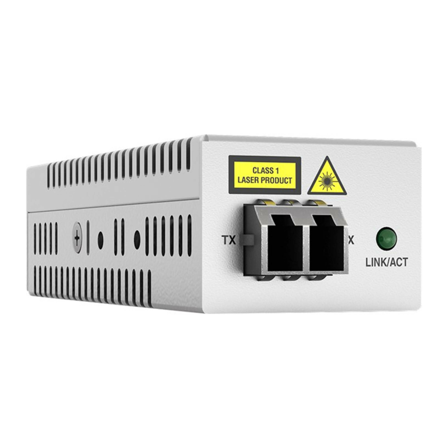
DMC1000/100 Series Media Converters Installation Guide Figure 3 illustrates the front panel of the AT-DMC1000/LC and AT-DMC100/LC Media Converters. Fiber LC TX & RX Ports Fiber Port LINK/ACT LED Figure 3. AT-DMC1000/LC and AT-DMC100/LC Front Panel Back Panel Figure 4 illustrates the media converter back panel. -
Page 18: Bottom Panels
Chapter 1: Overview Bottom Panels Figure 5 illustrates the bottom panel of the DMC1000/100 V1 series media converter. The DIP switch is for the SML mode ON or OFF. DIP Switch Figure 5. Bottom Panel of the DMC1000/100 V1 Series Figure 6 illustrates the bottom panel of the DMC1000/100 V2 series media converter. -
Page 19: Features
DMC1000/100 Series Media Converters Installation Guide Features Here are the features of the DMC1000/100 Series Mini Media Converters: Provide a smaller-sized space-saving alternative that allows enterprises to connect 1000Mbps fiber networks to 1000Mbps copper networks or connect 100Mbps fiber networks to 100Mbps copper networks, offering a cost-effective method for integrating fiber-optic cabling into a 10/100/1000 or 10/100 UTP environment. -
Page 20: Twisted-Pair Port
Depending on the customer order, the AC/DC power adapter is included with the media converter for standalone operation. The power adapter supplies 5 VDC to the media converter. Allied Telesis supplies a UL approved safety-compliant AC power adapter for the 120 and 240 VAC versions with a regulated output of 5 VDC. -
Page 21: Leds
DMC1000/100 Series Media Converters Installation Guide LEDs Figure 7 shows the SYS and copper port LEDs. LINK/ACT DUP/COL Figure 7. SYS and Copper Port LEDs Figure 8 shows the fiber port LED. AT-DMC1000/SC AT-DMC100/SC LINK/ACT AT-DMC1000/ST AT-DMC100/ST LINK/ACT AT-DMC1000/LC LINK/ACT AT-DMC100/LC Figure 8. -
Page 22: Table 2. Media Converter Led Functional Descriptions
Chapter 1: Overview Table 2 describes the media converter’s LEDs. Table 2. Media Converter LED Functional Descriptions State Description The media converter is not receiving power or is not operational. Solid Green The media converter is operational. (with Heartbeat) Note The SYS LED flickers briefly at a regular interval. - Page 23 DMC1000/100 Series Media Converters Installation Guide Table 2. Media Converter LED Functional Descriptions (Continued) State Description The port has not established a link. Steady Green The port has an established link to a network device, but it is not transmitting or receiving network packets.
-
Page 24: V1 And V2 Series Media Converters
Chapter 1: Overview V1 and V2 Series Media Converters The DMC1000/100 series media converters have two versions: V1 and V2. Both V1 and V2 have Smart MissingLink™ (SML). In addition to SML, the Missing Link (ML) feature is added to the V2 series media converters. -
Page 25: Differences Between V1 And V2
DMC1000/100 Series Media Converters Installation Guide To solve the above situation, ML is added to V2 series media converters, intended for use in standalone. Figure 11 illustrates the V2 series media converter in standalone in the ML mode. When the copper link fails, the fiber link goes down. -
Page 26: V1 Series Media Converters
The SML mode is intended when the fiber port is connected to another Allied Telesis media converter. Example The following example scenarios explain how the V1 series media... -
Page 27: V2 Series Media Converters
The SML mode is intended when the fiber port is connected to another Allied Telesis media converter. Example The following example scenarios explain how the V2 series media... -
Page 28: Smart Missinglink™ (Sml)
Chapter 1: Overview Smart MissingLink™ (SML) The Smart MissingLink™ (SML) feature makes a connection problem visible and helps you identify where troubleshooting is required. When one of the Ethernet connections to the media converter fails, SML disables the other port and causes its LED to blink to notify where a problem is occurring. -
Page 29: Standalone Media Converter In Sml Mode
DMC1000/100 Series Media Converters Installation Guide Figure 14 shows media converter and end node LINK/ACT LED behavior with SML off with a copper connection down. SML Off AT-DMC1000 End Node End Node Copper Cable Fiber Cable Copper Fiber LINK/ACT LINK/ACT... -
Page 30: Media Converters In Pairs In Sml Mode
Chapter 1: Overview Media Following are example scenarios with media converters in pairs in the SML mode, connected back-to-back or in the bookend mode. Converters in Pairs in SML Figure 18 shows media converter and its LINK/ACT LED behavior in the Mode SML mode under normal conditions. -
Page 31: Missing Link (Ml)
DMC1000/100 Series Media Converters Installation Guide Missing Link (ML) The DMC1000/100 V2 series media converters offer the Missing Link (ML), which is intended for use when the V2 media converter is connected standalone between a fiber endpoint and copper endpoint. -
Page 32: Figure 23: Ml With Copper Connection Down
Chapter 1: Overview Figure 23 shows media converter and its LINK/ACT LED behavior in the ML mode when a copper connection is down. When a copper connection to the media converter fails, the copper LINK/ACT LED is turned off. The fiber port LINK/ACT LED blinks slowly and the fiber link goes down. -
Page 33: Reset The Media Converter
DMC1000/100 Series Media Converters Installation Guide Reset the Media Converter Reset the media converter by powering the unit OFF, then ON. - Page 34 Chapter 1: Overview...
-
Page 35: Chapter 2 : Installation
Chapter 2 Installation This chapter contains the following sections: “Reviewing Safety Precautions” on page 36 “Selecting a Site for the Media Converter” on page 38 “Planning the Installation” on page 39 “Unpacking the Shipping Box” on page 40 ... -
Page 36: Reviewing Safety Precautions
Note indicates that a translation of the safety statement is available in a PDF document titled Translated Safety Statements on the Allied Telesis website at www.alliedtelesis.com/support. Warning Do not stare into the laser beam. Warning Do not look directly at the fiber-optic cable ends or inspect the cable ends with an optical lens. - Page 37 DMC1000/100 Series Media Converters Installation Guide Note The power input must be provided from SELV source only. Do not connect to a centralized DC battery bank. Caution Failing to pick up the ferrule tip when you reach the bottom of the cleaning surface can result in static electricity that can damage the fiber-optic cable.
-
Page 38: Selecting A Site For The Media Converter
Chapter 2: Installation Selecting a Site for the Media Converter Observe the following requirements when choosing a site for your media converter: If you are installing the media converter on a table, verify that the table is level and secure. The power outlet for the media converter should be located near ... -
Page 39: Planning The Installation
DMC1000/100 Series Media Converters Installation Guide Planning the Installation Be sure to observe the following guidelines when planning the installation of your media converter. The end node connected to the fiber connector on the AT-DMC1000 media converter must operate at 1000 Mbps. -
Page 40: Unpacking The Shipping Box
Chapter 2: Installation Unpacking the Shipping Box When unpacking the media converter shipping package or AT-DMCWLMT-005 wall-mount bracket kit, verify that the package includes the contents shown in this section. Guidelines Here are guidelines for unpacking the shipping box: Store the packaging material in a safe location. You must use the ... -
Page 41: Figure 25: At-Dmc1000/St And At-Dmc100/St Shipping Package Contents
DMC1000/100 Series Media Converters Installation Guide Figure 25 shows shipping container items for the AT-DMC1000/ST and AT-DMC100/ST. One USB cable One power adapter (depending on customer order) Two fiber port dust covers (pre-installed) Figure 25. AT-DMC1000/ST and AT-DMC100/ST Shipping Package... -
Page 42: Unpacking Theat-Dmcwlmt-005 Wall-Mount Bracket Kit
Chapter 2: Installation Unpacking To unpack the AT-DMCWLMT-005 wall-mount bracket kit, perform the following procedure: theAT-DMCWL MT-005 1. Remove all of the components from the shipping package. Wall-mount 2. verify that the shipping container includes the following items as Bracket Kit shown in Figure 27. -
Page 43: Installing The Media Converter
DMC1000/100 Series Media Converters Installation Guide Installing the Media Converter The DMC1000/100 Series media converter can be mounted on a desktop or a wall. Select one of the following procedures depending upon your mounting surface: “Installing the Media Converter on a Desktop,” next ... -
Page 44: Figure 28: Recommended Orientation
Chapter 2: Installation Cable Tie Notches Figure 28. Recommended Orientation 3. Use scotch tape to attach the template on the wall as shown in Figure 29. Figure 29. Placing the Template on the Wall 4. Use a Phillips-head screwdriver or hard and pointy object to mark two holes on the wall. -
Page 45: Figure 30: Securing The Mounting Bracket To The Wall
DMC1000/100 Series Media Converters Installation Guide 5. Remove the template from the wall. 6. Align the holes on the brackets to the marks on the wall. 7. Secure the bracket to the wall using two wall mounting screws as shown in Figure 30. -
Page 46: Figure 31: Attaching The Media Converter To The Mounting Bracket
Chapter 2: Installation Figure 31. Attaching the Media Converter to the Mounting Bracket 9. Secure the bracket to the media converter with the bracket screw included with the bracket. 10. Go to “Powering On and Cabling the Media Converter” on page 48. -
Page 47: Installing The Media Converter On A Sheetrock, Cinder Block, Or Concrete Wall
For the wall-mount template, see Appendix B on page 63. Allied Telesis recommends the bracket horizontally oriented with the cable tie notches facing either upward or downward. However, if there are space restrictions, the bracket may also be oriented vertically with the cable tie notches facing toward either the left or right. -
Page 48: Powering On And Cabling The Media Converter
Chapter 2: Installation Powering On and Cabling the Media Converter After installing the media converter on a desk or wall, next step is to power on and cable the media converter. Cabling Observe the following guidelines when connecting twisted-pair and fiber-optic cables to the ports on the media converter: Guidelines The connector on the cable should fit snugly into the port on the... -
Page 49: Figure 32: Securing The Usb Cable Tie
DMC1000/100 Series Media Converters Installation Guide Figure 32. Securing the USB Cable Tie 3. Do one of the following: Attach the other end of the USB cable to the USB port on a PC, as shown in Figure 33. -
Page 50: Figure 34: Connecting Power Via Power Adapter
Chapter 2: Installation Attach the other end of the USB cable to the USB port on the power adapter, then plug the power adapter to a power outlet, as shown in Figure 34. See “Power Specifications” on page 58 for power requirements. -
Page 51: Figure 35: Connecting Cable To Fiber Optic Port
DMC1000/100 Series Media Converters Installation Guide Figure 35. Connecting Cable to Fiber Optic Port 6. Verify that the media converter’s transmitter port (TX) is connected to the end node’s receiver port (RX) and that the media converter’s receiver port (RX) is connected to the end node’s transmitter port (TX). -
Page 52: Figure 36: Securing The Fiber Optic Cable Tie
Chapter 2: Installation Note Do not exceed the minimum bend radius of your fiber optic cable. See the manufacturer specifications for the minimum bend radius of your cable. c. Loop the cable tie around the cables. d. Fasten the cable tie. Figure 36. -
Page 53: Chapter 3 : Troubleshooting
This chapter contains information on how to troubleshoot the media converter if a problem occurs. Note For further assistance, please contact Allied Telesis Technical Support at www.alliedtelesis.com/support. Problem 1: The SYS LED on the media converter is off. Solutions: The unit is not receiving power. Try the following: Verify that the power cord is securely connected to the power ... - Page 54 Chapter 3: Troubleshooting Try connecting another end node to the twisted-pair port with a different cable. If the twisted-pair port is able to establish a link, then the problem is with the cable or the other end-node. Verify that the twisted-pair cable does not exceed 100 meters (328 ...
- Page 55 DMC1000/100 Series Media Converters Installation Guide Problem 5: Network performance between the twisted-pair port on the media converter and an end node is slow. Solution: Check the DUP/COL LED: if it is off and occasionally blinking, there might be a duplex-mode mismatch between the port and the end node.
- Page 56 Chapter 3: Troubleshooting...
-
Page 57: Appendix A: Technical Specifications
“RJ45 Connector and Port Pinouts” on page 59 “Fiber-Optic Port Specifications” on page 61 Physical Specifications DMC1000/100 Series Media Converter Table 4. Physical Specifications Dimensions 3.2 cm x 9.1 cm x 2.2 cm W x D x H (1.3 in x 3.6 in x 0.9 in) -
Page 58: Power Specifications
Appendix A: Technical Specifications Power Specifications The following specifications apply to the DC power connector on the media converter. Table 6. Power Specifications Input supply voltage 5 VDC Input current 0.5 A Environmental Specifications Table 7. Environmental Specifications Operating Temperature 0°... -
Page 59: Rj45 Connector And Port Pinouts
DMC1000/100 Series Media Converters Installation Guide RJ45 Connector and Port Pinouts Figure 37 illustrates the pin layout for the RJ45 connector and port. Figure 37. RJ45 Connector and Port Pin Layout Table 8 lists the pin signals when a port is operating in the MDI configuration at 100 Mbps. -
Page 60: Table 10. Pin Signals (1000 Mbps)
Appendix A: Technical Specifications Table 10 lists the pin signals when a port is operating at 1000 Mbps. Table 10. Pin Signals (1000 Mbps) Pair Signal TX and RX+ TX and RX- TX and RX+ TX and RX+ TX and RX- TX and RX- TX and RX+ TX and RX-... -
Page 61: Fiber-Optic Port Specifications
DMC1000/100 Series Media Converters Installation Guide Fiber-Optic Port Specifications The fiber type for the media converter is multimode. Table 11 lists fiber-optic port specifications for the AT-DMC1000/SC, AT-DMC1000/ST, and AT-DMC1000/LC media converters. Table 11. AT-DMC1000 Fiber-Optic Port Specifications Launch Power... - Page 62 Appendix A: Technical Specifications...
-
Page 63: Appendix B: Wall-Mount Template
Appendix B Wall-mount Template When installing the media converter on a wall, use the template shown in Figure 38 as a guide. 32.0mm [1.26in] 4408 Figure 38. Wall-mount Template... - Page 64 Appendix B: Wall-mount Template...
Need help?
Do you have a question about the DMC1000/100 Series and is the answer not in the manual?
Questions and answers