
Subscribe to Our Youtube Channel
Related Manuals for Allied Telesis AT-MMC1000/SP


Summary of Contents for Allied Telesis AT-MMC1000/SP
- Page 1 AT-MMC1000/SP Mini Switching Media Converters S F P C L A L A S P O R S S 1 E R P R O D U C T P O R 3645 Installation Guide 613-002949 Rev. A...
- Page 2 Allied Telesis, Inc. has been advised of, known, or should have known, the...
- Page 3 Electrical Safety and Emissions Standards This section contains the following: “US Federal Communications Commission” “Industry Canada” “Electrical Safety Standards” on page 4 “Translated Safety Statements” on page 4 US Federal Communications Commission Radiated Energy Note This equipment has been tested and found to comply with the limits for a Class A digital device pursuant to Part 15 of FCC Rules.
- Page 4 EN61000-4-3:2006 + A1:2008 + A2:2010 EN61000-4-4:2012 EN61000-4-5:2014 EN61000-4-6:2014 EN61000-4-8:2010 EN61000-4-11:2004 EN61000-3-2:2014 EN61000-3-3:2013 Translated Safety Statements Important: The indicates that a translation of the safety statement is available in a PDF document titled Translated Safety Statements on the Allied Telesis website at www.alliedtelesis.com/support.
-
Page 5: Table Of Contents
Contents Preface................................11 Symbol Conventions ..........................12 Contacting Allied Telesis..........................13 Chapter 1 : Overview ............................. 15 Introduction ..............................16 Features .............................. 17 Twisted-Pair Port ..........................18 Auto MDI/MDI-X ..........................18 Auto-Negotiation or 100 Mbps Full-Duplex Mode................18 External AC/DC Power Adapter ......................19 Supported SFP Modules ........................ - Page 6 Contents...
- Page 7 Figure 7: SML with Copper Connection to End Node Down....................24 Figure 8: SML with Fiber Connection Between Media Converters Down................24 Figure 9: AT-MMC1000/SP Media Converter Rear Panel DIP Switches ................25 Figure 10: Power Adapter in the Shipping Package ......................33 Figure 11: Inserting the SFP..............................
- Page 8 List of Figures...
- Page 9 Tables Table 1. Media Converter LED Functional Descriptions .....................22 Table 2. Twisted-Pair Port Cabling Specifications ......................31 Table 3. Copper Connection Speed/Duplex Settings and Resulting Speed ............... 32 Table 4. Physical Specifications ............................43 Table 5. Environmental Specifications ..........................43 Table 6. Power Specifications ............................44 Table 7.
- Page 10 List of Tables...
-
Page 11: Preface
Preface This preface contains the following sections: “Symbol Conventions” on page 12 “Contacting Allied Telesis” on page 13 This guide is the installation instructions for the AT-MMC1000/SP Mini Switching Media Converter. -
Page 12: Symbol Conventions
Symbol Conventions This document uses the following conventions: Note Notes provide additional information. Caution Cautions inform you that performing or omitting a specific action may result in equipment damage or loss of data. Warning Warnings inform you that performing or omitting a specific action may result in bodily injury. -
Page 13: Contacting Allied Telesis
AT-MMC1000 Mini Switching Media Converter Installation Guide Contacting Allied Telesis If you need assistance with this product, you may contact Allied Telesis technical support by going to the Services & Support section of the Allied Telesis web site at www.alliedtelesis.com/support. You can find links for... -
Page 15: Chapter 1 : Overview
Chapter 1 Overview This chapter contains the following sections: “Introduction” on page 16 “LEDs” on page 21 “Smart MissingLink™ (SML)” on page 23 “Reset the Media Converter” on page 26 ... -
Page 16: Introduction
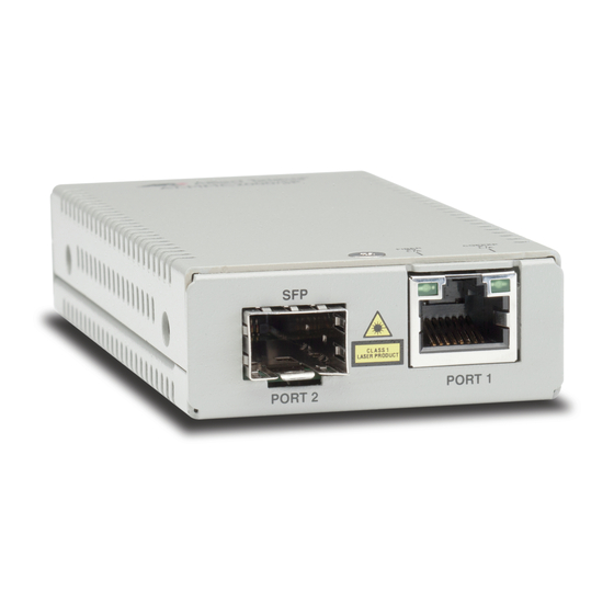
Chapter 1: Overview Introduction The AT-MMC1000/SP Mini Switching Media Converter as shown in Figure 1 is equipped with to a twisted pair port and SFP slot to allow enterprises to connect copper networks to fiber networks and extend the distance of these networks by interconnecting LAN devices physically separated by large distances. -
Page 17: Features
SYS LED 100Mbps Full Duplex/ Auto Negotiation DIP Switch Figure 3. Media Converter Back Panel Features Here are the key features of the AT-MMC1000/SP media converter: Space-saving small device Cost-effective method for integrating from 100M/1GBase-T to 100M/1GBase-TX environment Smart MissingLink™... -
Page 18: Twisted-Pair Port
Chapter 1: Overview Twisted-Pair Port Here are the basic features of the twisted-pair (copper) port: IEEE 802.3u Auto-Negotiation compliant Auto MDI/MDI-X 100 meters (328 feet) maximum operating distance RJ45 connector The twisted-pair port features an eight-pin RJ45 connector that uses four pins at 10 or 100 Mbps and all eight pins at 1000 Mbps. -
Page 19: External Ac/Dc Power Adapter
The power adapter supplies 12 VDC to the media Power Adapter converter. Allied Telesis supplies a UL approved safety compliant AC power adapter for the 120 and 240 VAC versions with a regulated output of 12 VDC. The power required for the media converter is 12 VDC, 200 mA and the power adapter complies with LPS/PS2 requirements. - Page 20 Chapter 1: Overview AT-SPFXBD-LC-13 AT-SPFXBD-LC-15 AT-SPFX/2(V2) AT-SPFX30/I AT-SPBD20LC/I-13 AT-SPBD20LC/I-14 ...
-
Page 21: Leds
AT-MMC1000 Mini Switching Media Converter Installation Guide LEDs Figure 4 shows the PWR and SYS LEDs on the back panel. Power LED System LED Figure 4. PWR and SYS LEDs Figure 5 shows the port LEDs on the front panel. FIBER COPPER Figure 5. -
Page 22: Table 1. Media Converter Led Functional Descriptions
A = Activity) Slow Blinking SML is on and detects a failure on the copper Green port or the remote fiber port when operating in a back-to-back configuration with another AT-MMC1000/SP or an AT-MMC2000/SP media converter. See Figure 7 on page 24. -
Page 23: Smart Missinglink™ (Sml)
AT-MMC2000/SP media converter. The SFP modules installed on the two media converters must be the same model. You must disable SML on the AT-MMC1000/SP media converter if the other media converter is not an AT-MMC1000/SP or AT-MMC2000/SP media converter. -
Page 24: Figure 6: Sml In Normal Condition With Two Media Converters
Chapter 1: Overview End Node AT-MMC1000/SP AT-MMC1000/SP End Node Copper L/A Fiber L/A Fiber L/A Copper L/A Link LED On Link LED On LED On LED On LED On LED On Copper Cable Fiber Cable Copper Cable Figure 6. SML in Normal Condition with Two Media Converters... -
Page 25: Enabling Sml
ON (up) position. See Figure 9. SML ON/OFF PORT 1 (In Auto Negotiation position) Figure 9. AT-MMC1000/SP Media Converter Rear Panel DIP Switches Note For information on the FORCE 100 F/D and AUTO NEG switch, see “Auto-Negotiation or 100 Mbps Full-Duplex Mode” on page 18. -
Page 26: Reset The Media Converter
Chapter 1: Overview Reset the Media Converter Reset the media converter by powering OFF then powering ON the unit. -
Page 27: Chapter 2 : Installation
Chapter 2 Installation This chapter contains the following sections: “Reviewing Safety Precautions” on page 28 “Selecting a Site for the Media Converter” on page 30 “Planning the Installation” on page 31 “Unpacking the Media Converter” on page 33 ... -
Page 28: Reviewing Safety Precautions
available in a PDF document titled Translated Safety Statements on the Allied Telesis website at www.alliedtelesis.com/support. Caution Air vents must not be blocked and must have free access to the room ambient air for cooling. - Page 29 AT-MMC1000 Mini Switching Media Converter Installation Guide Warning In a domestic environment this product may cause radio interference in which case the user may be required to take adequate measures. Warning An SFP transceiver can be damaged by static electricity. Be sure to observe all standard electrostatic discharge (ESD) precautions, such as wearing an antistatic wrist strap, to avoid damaging the transceiver.
-
Page 30: Selecting A Site For The Media Converter
Chapter 2: Installation Selecting a Site for the Media Converter Observe the following requirements when choosing a site for your media converter: If you are installing the media converter on a table, verify that the table is level and secure. The power outlet for the media converter should be located near ... -
Page 31: Planning The Installation
The twisted-pair port has a maximum operating distance of 100 meters (328 feet). The maximum operating distance of the AT-MMC1000/SP media converter is dependent on the specific SFP module. 100Mbps and 1Gbps SFP modules are supported. ... -
Page 32: Table 3. Copper Connection Speed/Duplex Settings And Resulting Speed
Chapter 2: Installation For speed/duplex interactions between the copper port on the AT-MMC1000/SP media converter and the copper link partner, see Table 3 for allowable speed/duplex combinations. Table 3. Copper Connection Speed/Duplex Settings and Resulting Speed Copper Port Speed/Duplex Copper Link Partner Port Setting... -
Page 33: Unpacking The Media Converter
AT-MMC1000 Mini Switching Media Converter Installation Guide Unpacking the Media Converter To unpack the media converter, perform the following procedure: 1. Remove all of the components from the shipping package. Note Store the packaging material in a safe location. You must use the original shipping material if you need to return the unit to Allied Telesis. -
Page 34: Installing The Media Converter
To install the media converter on an equipment rack using the AT-MMCR18 rack mount kit, see “Installation Guide: AT-MMCR18 Media Converter Rack-Mount Chassis” on Allied Telesis website. Note To install the media converter on an equipment rack using the AT-MMCR18 rack mount kit, you must purchase the kit separately. -
Page 35: Installing The Sfp Transceiver
AT-MMC1000 Mini Switching Media Converter Installation Guide Installing the SFP Transceiver To install an SFP transceiver, perform the following procedure: Note The transceiver can be hot-swapped; you do not need to power off the media converter to install a transceiver. However, always remove the cable before removing the transceiver. -
Page 36: Figure 11: Inserting The Sfp
Chapter 2: Installation Figure 11. Inserting the SFP 4. Verify that the handle on the transceiver is in the upright position, as shown in Figure 12. This secures the transceiver and prevents it from being dislodged from the slot. SFP Transceiver Handle Figure 12. -
Page 37: Powering On And Cabling The Media Converter
AT-MMC1000 Mini Switching Media Converter Installation Guide Powering On and Cabling the Media Converter Cabling Observe the following guidelines when connecting twisted-pair and fiber- optic cables to the ports on the media converter: Guidelines The connector on the cable should fit snugly into the port on the ... - Page 38 Chapter 2: Installation 2. Plug the power adapter to a power outlet. Refer to “Power Specifications” on page 44 for power requirements. 3. Verify that the PWR LED is lit green. If the PWR LED is off, refer to “Troubleshooting” on page 39. 4.
-
Page 39: Chapter 3 : Troubleshooting
This chapter contains information on how to troubleshoot the media converter if a problem occurs. Note For further assistance, please contact Allied Telesis Technical Support at www.alliedtelesis.com/support. Problem 1: The POWER LED on the media converter is off. Solutions: The unit is not receiving power. Try the following: Verify that the power cord is securely connected to the power ... - Page 40 Chapter 3: Troubleshooting Problem 4: The twisted-pair port on the media converter is connected to an end node, but the port’s COPPER P1 L/A LED is off. Solutions: The port is unable to establish a link to an end node. Try the following: Verify that the end node connected to the twisted-pair port is ...
- Page 41 AT-MMC1000 Mini Switching Media Converter Installation Guide Verify that the operating specifications and wave lengths of the fiber-optic port on the SFP transceiver and the remote end-node are compatible. Verify that the correct type of fiber-optic cabling is being used. ...
- Page 42 Chapter 3: Troubleshooting...
-
Page 43: Appendix A: Technical Specifications
Appendix A Technical Specifications Below are the technical specifications for the media converters. The specification categories are as follows: “Physical Specifications” “Environmental Specifications” “Power Specifications” on page 44 “RJ45 Connector and Port Pinouts” on page 44 Physical Specifications Table 4. -
Page 44: Power Specifications
Appendix A: Technical Specifications Power Specifications The following specifications apply to the DC power connector on the media converter. Table 6. Power Specifications Input supply voltage 12 VDC Input current 0.7 A RJ45 Connector and Port Pinouts Figure 14 illustrates the pin layout for the RJ45 connector and port. Figure 14. -
Page 45: Table 8. Mdi-X Pin Signals (10 Or 100 Mbps)
AT-MMC1000 Mini Switching Media Converter Installation Guide Table 8 lists the pin signals when a port is operating in the MDI-X configuration at 10 or 100 Mbps. Table 8. MDI-X Pin Signals (10 or 100 Mbps) Signal Table 9 lists the pin signals when a port is operating at 1000 Mbps. Table 9. - Page 46 Appendix A: Technical Specifications...
-
Page 47: Appendix B: At-Mmcwlmt Kit Installation
Appendix B AT-MMCWLMT Kit Installation Before installing an MMC media converter on a wall, you must have an AT-MMCWLMT Kit that is provided separately. When installing a media converter on a wood wall, you must provide four 4x32mm wood screws per media converter in addition to the AT-MMCWLMT Kit. -
Page 48: Figure 15: Attaching The Brackets To The Media Converter
Appendix B: AT-MMCWLMT Kit Installation 4. Orient the brackets against the sides of the unit, as shown in step 15, and secure them to the unit with the four of the brackets screws included. Figure 15. Attaching the Brackets to the Media Converter 5. -
Page 49: Figure 17: Placing The Template On The Wall
AT-MMC1000 Mini Switching Media Converter Installation Guide 6. Use scotch tape to attach the template on the wall. 7. Pre-drill four 3/16” (5mm) holes at the locations on the templates as shown in Figure 17. Figure 17. Placing the Template on the Wall 8. -
Page 50: Figure 18: Securing The Media Converter To The Wall
Appendix B: AT-MMCWLMT Kit Installation Figure 18. Securing the Media Converter to the Wall...
Need help?
Do you have a question about the AT-MMC1000/SP and is the answer not in the manual?
Questions and answers