Allied Telesis MMC2000 Series Installation Manual

Allied Telesis MMC2000 Series Installation Manual

Mini switching media converters
Table of Contents

Advertisement

MMC2000/200 Series
Mini Switching Media Converters
AT-MMC2000/SC
AT-MMC2000/ST
AT-MMC2000/LC
AT-MMC2000/SP
AT-MMC2000LX/SC
AT-MMC2000LX/LC
AT-MMC2000/T
AT-MMC200/SC
AT-MMC200/ST
AT-MMC200/LC
AT-MMC200LX/SC
AT-MMC200LX/ST
Installation Guide
613-002037 Rev. F

Advertisement

Table of Contents
loading

Summary of Contents for Allied Telesis MMC2000 Series

  • Page 1 MMC2000/200 Series Mini Switching Media Converters AT-MMC2000/SC  AT-MMC2000/ST  AT-MMC2000/LC  AT-MMC2000/SP  AT-MMC2000LX/SC  AT-MMC2000LX/LC  AT-MMC2000/T  AT-MMC200/SC  AT-MMC200/ST  AT-MMC200/LC  AT-MMC200LX/SC  AT-MMC200LX/ST  Installation Guide 613-002037 Rev. F...
  • Page 2 Allied Telesis, Inc. has been advised of, known, or should have known, the...
  • Page 3 Electrical Safety and Emissions Standards This section contains the following: “US Federal Communications Commission”  “Safety Standards and Electromagnetic Compatibility” on page 3  “Translated Safety Statements” on page 4  US Federal Communications Commission Radiated Energy Note This equipment has been tested and found to comply with the limits for a Class A digital device pursuant to Part 15 of FCC Rules.
  • Page 4 Translated Safety Statements Important: The indicates that a translation of the safety statement is available in a PDF  document titled Translated Safety Statements on the Allied Telesis website at www.alliedtelesis.com/support.
  • Page 5: Table Of Contents

    Contents Preface................................11 Symbol Conventions ..........................12 Contacting Allied Telesis..........................13 Chapter 1 : Overview ............................. 15 Introduction ..............................16 Front Panels ............................16 Back Panel ............................19 Features ..............................20 Twisted-Pair Port ..........................22 Auto MDI/MDI-X ..........................22 Auto-Negotiation or 100 Mbps Full-Duplex Mode................22 External AC/DC Power Adapter ......................
  • Page 6 Contents Power Specifications ..........................58 RJ45 Connector and Port Pinouts ......................58 Fiber-Optic Port Specifications ........................60 Appendix B: AT-MMCWLMT Kit Installation ....................63...
  • Page 7 Figures Figure 1: Front Panel for the MMC2000/200 Series Media Converters with the SC Connector.......... 16 Figure 2: Front Panel for the MMC2000/200 Series Media Converters with the ST Connector .......... 17 
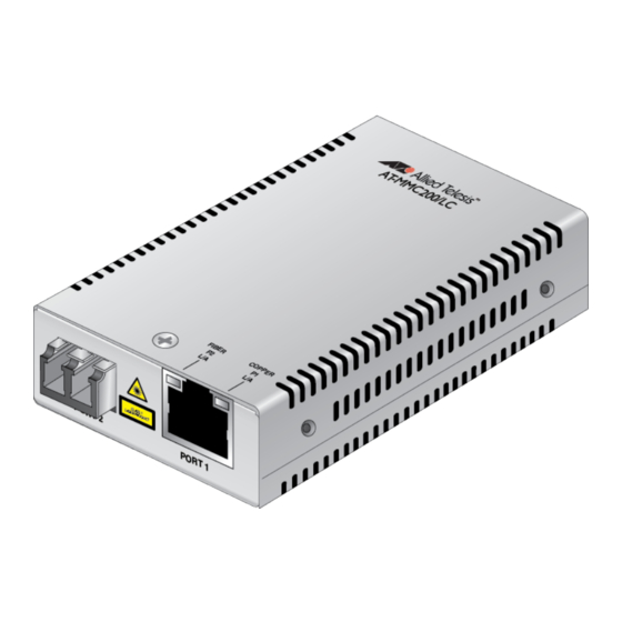
Figure 3: Front Panel for the MMC2000/200 Series Media Converters with the LC Connector .......... 17 Figure 4: AT-MMC2000/SP Front Panel..........................
  • Page 8 List of Figures...
  • Page 9 Tables Table 1. Port Specifications for the MMC2000/200 Series ....................20 Table 2. Port Specifications for the AT-MMC2000/T Model ....................21 Table 3. Media Converter LED on the Back Panel ......................24 Table 4. Port LEDs for the MMC2000/200 Series with a Fiber Port ................... 25 Table 5.
  • Page 10 List of Tables...
  • Page 11: Preface

    Preface This preface contains the following sections: “Symbol Conventions” on page 12  “Contacting Allied Telesis” on page 13  This guide contains the installation instructions for the following Mini Switching Media Converters. AT-MMC2000/SC  AT-MMC2000/ST  AT-MMC2000/SP  AT-MMC2000/LC ...
  • Page 12: Symbol Conventions

    Symbol Conventions This document uses the following conventions: Note Notes provide additional information. Caution Cautions inform you that performing or omitting a specific action may result in equipment damage or loss of data. Warning Warnings inform you that performing or omitting a specific action may result in bodily injury.
  • Page 13: Contacting Allied Telesis

     guides, software release notes, white papers and data sheets for your product. Warranty - View a list of products to see if Allied Telesis warranty  applies to the product you purchased and register your warranty. Allied Telesis Helpdesk - Contact a support representative.
  • Page 15: Chapter 1 : Overview

    Chapter 1 Overview This chapter contains the following sections: “Introduction” on page 16  “Features” on page 20  “LEDs” on page 24  “V2 and V3 Series Media Converters” on page 27  “V2 Series Media Converters” on page 29 ...
  • Page 16: Introduction

    Chapter 1: Overview Introduction The MMC2000/200 Series Mini Switching Media Converters are designed to extend the distance of your network by interconnecting LAN devices that are physically separated by large distances. The MMC2000/200 Series Mini Switching Media Converters include the following models: AT-MMC2000/SC ...
  • Page 17: Figure 2: Front Panel For The Mmc2000/200 Series Media Converters With The St Connector

    MMC2000/200 Series Mini Switching Media Converter Installation Guide Figure 2 illustrates the front panel of the AT-MMC2000/ST, AT-MMC200/ST, and AT-MMC200LX/ST media converters. Base-T Fiber ST TX & RX Twisted-Pair Port L/A LED Ports Fiber Port L/A LED Base-T Twisted-Pair Port Figure 2.
  • Page 18: Figure 4: At-Mmc2000/Sp Front Panel

    Chapter 1: Overview Figure 4 illustrates the front panel of the AT-MMC2000/SP media converter. 10/100/1000Base-T Fiber SP SFP Twisted-Pair Port Slot L/A LED Fiber Port L/A LED 10/100/1000Base-T Twisted-Pair Port Figure 4. AT-MMC2000/SP Front Panel Figure 5 illustrates the front panel of the AT-MMC2000/T media converter. 10/100/1000Base-T Twisted-Pair Port L/A LED 10/100/1000Base-T...
  • Page 19: Back Panel

    MMC2000/200 Series Mini Switching Media Converter Installation Guide Back Panel Figure 6 illustrates the back panel of the MMC2000/200 V2 series media converter. SML On/Off 12 VDC Input PWR LED DIP Switch SYS LED 100Mbps Full Duplex/Auto Negotiation DIP Switch Figure 6.
  • Page 20: Features

    Chapter 1: Overview Features Here are the key features of the MMC2000/200 Series converters: The media converter provides a smaller-sized space-saving  alternative to connect networks. The MMC2000/200 Series media converters except the  AT-MMC2000/T model allow enterprises to connect copper networks to fiber networks, offering a cost-effective method for integrating fiber-optic cabling into a 10/100/1000 or 10/100 UTP environment.
  • Page 21: Table 2. Port Specifications For The At-Mmc2000/T Model

    100Mbps and 1Gbps modules are supported. Note For the AT-MMC2000/SP model, you must purchase the SFP transceiver separately. The maximum operating distance of the AT-MMC2000/SP is dependent on the specific SFP module. For a list of supported transceivers, contact your Allied Telesis distributor or reseller.
  • Page 22: Twisted-Pair Port

    Chapter 1: Overview Twisted-Pair Port Here are the basic features of the twisted-pair (copper) port: IEEE 802.3u Auto-Negotiation compliant  Auto MDI/MDI-X  100 meters (328 feet) maximum operating distance  RJ45 connector  The twisted-pair port features an eight-pin RJ45 connector that uses four pins at 10 or 100 Mbps and all eight pins at 1000 Mbps.
  • Page 23: External Ac/Dc Power Adapter

    The power adapter supplies 12 VDC to the media Power Adapter converter. Allied Telesis supplies a UL approved safety compliant AC power adapter for the 120 and 240 VAC versions with a regulated output of 12 VDC. The power required for the media converter is 12 VDC, 200...
  • Page 24: Leds

    Chapter 1: Overview LEDs Figure 8 shows the PWR and SYS LEDs on the back panel. Figure 8. PWR and SYS LEDs on the Back Panel Table 3 describes the media converter’s LEDs on the back panel. Table 3. Media Converter LED on the Back Panel State Description The media converter is not receiving power.
  • Page 25: Figure 9: Port Leds On The Mmc2000/200 Series With A Fiber Port

    MMC2000/200 Series Mini Switching Media Converter Installation Guide Figure 9 shows the port LEDs on the MMC2000/200 Series media converters except the AT-MMC2000/T model. FIBER COPPER Figure 9. Port LEDs on the MMC2000/200 Series with a Fiber Port Table 4 describes the port LEDs on the MMC2000/200 series media converters except the AT-MMC2000/T model.
  • Page 26: Figure 10: Port Leds On The At-Mmc2000/T Model

    Chapter 1: Overview Figure 10 shows the port LEDs on the AT-MMC2000/T media converter. Figure 10. Port LEDs on the AT-MMC2000/T Model Table 5 describes the port LEDs on the AT-MMC2000/T model. Table 5. Port LEDs for the AT-MMC2000/T Model State Description The port has not established a link.
  • Page 27: V2 And V3 Series Media Converters

    MMC2000/200 Series Mini Switching Media Converter Installation Guide V2 and V3 Series Media Converters The MMC2000/200 series media converters have two versions: V2 and V3. Both V2 and V3 have Smart MissingLink™ (SML). In addition to SML, the Missing Link (ML) feature is added to the V3 series media converters. SML passes a link status from one port to the other so that user’s managed endpoints can detect a failure at links where the endpoints are not directly connected.
  • Page 28: Differences Between V2 And V3

    Chapter 1: Overview To solve the above situation, ML is added to V3 series media converters, intended for use in standalone. Figure 13 illustrates the V3 series media converter in standalone in the ML mode. When the copper link fails, the fiber link goes down. ML On MMC2000/200 V3 End Node...
  • Page 29: V2 Series Media Converters

    The SML mode is intended when the fiber port is connected to another Allied Telesis media converter. Example The following example scenarios explain how the V2 series media...
  • Page 30: V3 Series Media Converters

    The SML mode is intended when the fiber port is connected to another Allied Telesis media converter. Example The following example scenarios explain how the V3 series media...
  • Page 31: Smart Missinglinkā„¢ (Sml)

    MMC2000/200 Series Mini Switching Media Converter Installation Guide Smart MissingLink™ (SML) The Smart MissingLink™ (SML) feature makes a connection problem visible and helps you identify where troubleshooting is required. When one of the Ethernet connections to the media converter fails, SML disables the other port and causes its LED to blink to notify where a problem is occurring.
  • Page 32: Standalone Media Converter In Sml Mode

    Chapter 1: Overview Figure 16 shows media converter and end node LINK/ACT LED behavior with SML off with a copper connection down. SML Off AT-MMC2000 V2 End Node End Node Copper Cable Fiber Cable Copper Fiber LINK/ACT LINK/ACT Link LED Off Link Down Link Up Link LED On...
  • Page 33: Media Converters In Pairs In Sml Mode

    MMC2000/200 Series Mini Switching Media Converter Installation Guide Media Following are example scenarios with media converters in pairs in the SML mode, connected back-to-back or in the bookend mode. Converters in Pairs in SML Figure 20 shows media converter and its LINK/ACT LED behavior in the Mode SML mode under normal conditions.
  • Page 34: Missing Link (Ml)

    Chapter 1: Overview Missing Link (ML) The MMC2000/200 V3 series media converters offer the Missing Link (ML), which is intended for use when the V2 media converter is connected standalone between a fiber endpoint and copper endpoint. Note To find out whether your device is V2 or V3, see “Differences Between V2 and V3”...
  • Page 35: Figure 25: Ml With Copper Connection Down

    MMC2000/200 Series Mini Switching Media Converter Installation Guide Figure 25 shows media converter and its LINK/ACT LED behavior in the ML mode when a copper connection is down. When a copper connection to the media converter fails, the copper LINK/ACT LED is turned off. The fiber port LINK/ACT LED blinks slowly and the fiber link goes down.
  • Page 36: Reset The Media Converter

    Chapter 1: Overview Reset the Media Converter Reset the media converter by powering OFF then powering ON the unit.
  • Page 37: Chapter 2 : Installation

    Chapter 2 Installation This chapter contains the following sections: “Reviewing Safety Precautions” on page 38  “Selecting a Site for the Media Converter” on page 40  “Planning the Installation” on page 41  “Unpacking the Media Converter” on page 44 ...
  • Page 38: Reviewing Safety Precautions

     available in a PDF document titled Translated Safety Statements on the Allied Telesis website at www.alliedtelesis.com/support. Caution Air vents must not be blocked and must have free access to the room ambient air for cooling.
  • Page 39 MMC2000/200 Series Mini Switching Media Converter Installation Guide Warning In a domestic environment this product may cause radio interference in which case the user may be required to take adequate measures.  Warning An SFP transceiver can be damaged by static electricity. Be sure to observe all standard electrostatic discharge (ESD) precautions, such as wearing an antistatic wrist strap, to avoid damaging the transceiver.
  • Page 40: Selecting A Site For The Media Converter

    Chapter 2: Installation Selecting a Site for the Media Converter Observe the following requirements when choosing a site for your media converter: If you are installing the media converter on a table, verify that the  table is level and secure. The power outlet for the media converter should be located near ...
  • Page 41: Planning The Installation

    MMC2000/200 Series Mini Switching Media Converter Installation Guide Planning the Installation Be sure to observe the following guidelines when planning the installation of your media converter. On the MMC2000 media converters, the end node connected to  the fiber connector on the media converter must operate at 1000 Mbps, except for the AT-MMC2000/SP when using a 100 Mbps SFP module.
  • Page 42: Table 7. Twisted-Pair Port Cabling Specifications

    Chapter 2: Installation Note For the AT-MMC2000/SP model, you must purchase the SFP transceiver separately. The maximum operating distance of the AT-MMC2000/SP media converter is dependent on the specific SFP module. For a list of supported transceivers, contact your Allied Telesis distributor or reseller.
  • Page 43: Table 8. Copper Connection Speed/Duplex Settings And Resulting Speed

    MMC2000/200 Series Mini Switching Media Converter Installation Guide Table 8. Copper Connection Speed/Duplex Settings and Resulting Speed MMC2000/200 Copper Port Copper Link Partner Port Setting Speed/Duplex Setting Auto Negotiation 100Mbps Force 100Mbps Force 1000Mbps Full Duplex Half Duplex Force Full Duplex* Auto Negotiation 1000Mbps full...
  • Page 44: Unpacking The Media Converter

    Chapter 2: Installation Unpacking the Media Converter To unpack the media converter, perform the following procedure: 1. Remove all of the components from the shipping package. Note Store the packaging material in a safe location. You must use the original shipping material if you need to return the unit to Allied Telesis.
  • Page 45: Figure 27: Mmc2000/200/St Series And At-Mmc200Lx/St Shipping Package Contents

    MMC2000/200 Series Mini Switching Media Converter Installation Guide Figure 27 shows shipping container items for the  MMC2000/200/ST series and AT-MMC200/LX/ST media converters. One power adapter Two fiber port dust covers (pre-installed) Figure 27. MMC2000/200/ST Series and AT-MMC200LX/ST Shipping Package Contents Figure 28 shows shipping container items for the ...
  • Page 46: Figure 29: At-Mmc2000/Sp Shipping Package Contents

    Chapter 2: Installation Figure 29 shows shipping container items for the  AT-MMC2000/SP model. One power adapter One SFP slot dust cover (pre-installed) Figure 29. AT-MMC2000/SP Shipping Package Contents Figure 30 shows shipping container items for the  AT-MMC2000/T model. One power adapter Figure 30.
  • Page 47: Installing The Media Converter

    MMC2000/200 Series Mini Switching Media Converter Installation Guide Installing the Media Converter You may install the media converter on a desktop or on a wall: To install the media converter on a desktop, see “Installing the  Media Converter on a Desktop,” next. To install the media converter on a wall, see “AT-MMCWLMT Kit ...
  • Page 48: Installing The Sfp Transceiver

    Chapter 2: Installation Installing the SFP Transceiver To install an SFP transceiver, perform the following procedure: Note The transceiver can be hot-swapped; you do not need to power off the media converter to install a transceiver. However, always remove the cable before removing the transceiver. Note You should always install the transceiver before connecting the fiber-optic cable to it.
  • Page 49: Figure 32: Inserting The Sfp

    MMC2000/200 Series Mini Switching Media Converter Installation Guide 4. Slide the transceiver into the SFP slot until it clicks into place. See Figure 32. Figure 32. Inserting the SFP 5. Verify that the handle on the transceiver is in the upright position, as shown in Figure 33.
  • Page 50 Chapter 2: Installation For information on the cable specifications of the SFP, consult the documentation shipped with the SFP. 6. Go to “Powering On and Cabling the Media Converter” on page 51.
  • Page 51: Powering On And Cabling The Media Converter

    MMC2000/200 Series Mini Switching Media Converter Installation Guide Powering On and Cabling the Media Converter Cabling Observe the following guidelines when connecting twisted-pair and fiber- optic cables to the ports on the media converter: Guidelines The connector on the cable should fit snugly into the port on the ...
  • Page 52 Chapter 2: Installation 2. Plug the power adapter to a power outlet. Refer to “Power Specifications” on page 58 for power requirements. 3. Verify that the PWR LED is lit green. If the PWR LED is off, refer to “Troubleshooting” on page 53. 4.
  • Page 53: Chapter 3 : Troubleshooting

    This chapter contains information on how to troubleshoot the media converter if a problem occurs. Note For further assistance, please contact Allied Telesis Technical Support at www.alliedtelesis.com/support. Problem 1: The POWER LED on the media converter is off. Solutions: The unit is not receiving power. Try the following: Verify that the power cord is securely connected to the power ...
  • Page 54 Chapter 3: Troubleshooting Problem 4: The twisted-pair port on the media converter is connected to an end node, but the port’s COPPER P1 L/A LED is off. Solutions: The port is unable to establish a link to an end node. Try the following: Verify that the end node connected to the twisted-pair port is ...
  • Page 55 MMC2000/200 Series Mini Switching Media Converter Installation Guide Verify that the media converter’s transmitter port (TX) is connected  to the end node’s receiver port (RX) and that the media converter’s receiver port (RX) is connected to the end node’s transmitter port (TX).
  • Page 56 Chapter 3: Troubleshooting...
  • Page 57: Appendix A: Technical Specifications

    Appendix A Technical Specifications Below are the technical specifications for the media converters. The specification categories are as follows: “Physical Specifications”  “Environmental Specifications”  “Power Specifications” on page 58  “RJ45 Connector and Port Pinouts” on page 58  “Fiber-Optic Port Specifications”...
  • Page 58: Power Specifications

    Appendix A: Technical Specifications Power Specifications The following specifications apply to the DC power connector on the media converter. Table 11. Power Specifications Input supply voltage 12 VDC RJ45 Connector and Port Pinouts Figure 35 illustrates the pin layout for the RJ45 connector and port. Figure 35.
  • Page 59: Table 13. Mdi-X Pin Signals (10 Or 100 Mbps)

    MMC2000/200 Series Mini Switching Media Converter Installation Guide Table 13 lists the pin signals when a port is operating in the MDI-X configuration at 10 or 100 Mbps. Table 13. MDI-X Pin Signals (10 or 100 Mbps) Pair Signal Table 14 lists the pin signals when a port is operating at 1000 Mbps. Table 14.
  • Page 60: Fiber-Optic Port Specifications

    Appendix A: Technical Specifications Fiber-Optic Port Specifications Note Fiber optic port specifications for the AT-MMC2000/SP are dependent upon the type of SFP inserted. The fiber types for the MMC2000/200 series media converters are shown in Table 15. Table 15. Fiber Type Models Fiber Type AT-MMC2000/LC...
  • Page 61: Table 17. At-Mmc200 Fiber-Optic Port Specifications

    MMC2000/200 Series Mini Switching Media Converter Installation Guide Table 17 lists fiber-optic port specifications for the AT-MMC200 media converters. Table 17. AT-MMC200 Fiber-Optic Port Specifications Launch Power Fiber Receive Power Optical Max. Optic (dBm) (dBm) Wavelength Diameter Distance (nm) (microns) Min.
  • Page 62 Appendix A: Technical Specifications...
  • Page 63: Appendix B: At-Mmcwlmt Kit Installation

    Appendix B AT-MMCWLMT Kit Installation Before installing an MMC media converter on a wall, you must have an AT-MMCWLMT Kit that is provided separately. 1. Verify that the AT-MMCWLMT Kit contains the items shown in Table 20. Table 20 AT-MMCR WLMT Kit Contents Description Illustration 5 Sets of Wall...
  • Page 64: Figure 36: Attaching The Brackets To The Media Converter

    Appendix B: AT-MMCWLMT Kit Installation 4. Orient the brackets against the sides of the unit, as shown in Figure 36, and secure them to the unit with the four of the brackets screws included. Figure 36. Attaching the Brackets to the Media Converter 5.
  • Page 65: Figure 38: Placing The Template On The Wall

    MMC2000/200 Series Mini Switching Media Converter Installation Guide 6. Use scotch tape to attach the template on the wall. 7. Pre-drill four 3/16” (5mm) holes at the locations on the templates as shown in Figure 38. Figure 38. Placing the Template on the Wall 8.
  • Page 66: Figure 39: Securing The Media Converter To The Wall

    Appendix B: AT-MMCWLMT Kit Installation Figure 39. Securing the Media Converter to the Wall...

Table of Contents